4 prong relay
Printed From: the12volt.com
Forum Name: Relays
Forum Discription: Relay Diagrams, SPDT Relays, SPST Relays, DPDT Relays, Latching Relays, etc.
URL: https://www.the12volt.com/installbay/forum_posts.asp?tid=84638
Printed Date: February 06, 2026 at 6:25 AM
Topic: 4 prong relay
Posted By: BLT79
Subject: 4 prong relay
Date Posted: October 25, 2006 at 6:47 PM
I have a keyless entry system with relays on board in my truck. I just added a remote start system but the lock/unlock function will not tie into the keyless entry system. I can wire a relay for the RS system lock/unlock, but I can only get 4 prong relays in the small town that I live in. My problem is I don't know how to properly wire a four prong relay.
Replies:
Posted By: BLT79
Date Posted: October 25, 2006 at 7:02 PM
So wiring for a 2 wire aftermarket door lock actuators using a four prong relay is what I'm looking for.
Posted By: sparkie
Date Posted: October 25, 2006 at 7:42 PM
It can't be done. You must get the correct relays.
-------------
sparky
Posted By: hotwaterwizard
Date Posted: October 26, 2006 at 11:49 PM
why can't it be done?
-------------
John DeRosa (Hotwaterwizard)
Stockton California
When in doubt, try it out !
Posted By: cntrylvr79
Date Posted: October 27, 2006 at 8:43 AM
Because you can't 5 wire a door lock actuator with a 4 wire relay/
-------------
Cause I'm So white and nerdy...
First Class Certi-fried installer
Posted By: hotwaterwizard
Date Posted: October 27, 2006 at 10:27 PM
BLT79] wrote:
o wiring for a 2 wire aftermarket door lock actuators using a four prong relay is what I'm looking for.
Who said anything about a 5 wire setup? ------------- John DeRosa (Hotwaterwizard)
Stockton California
When in doubt, try it out !
Posted By: master5
Date Posted: October 27, 2006 at 11:01 PM
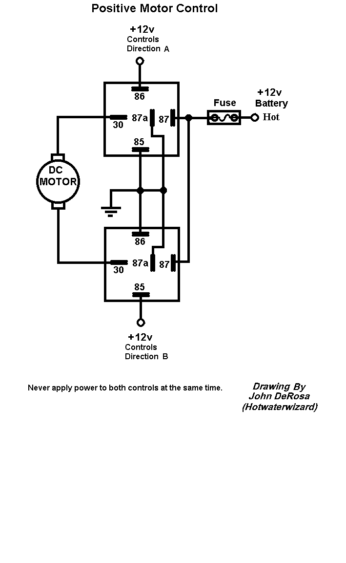
Another term for wiring an actuator to relays can be called a 5 wire setup, but realistically it is known as a (reversing polarity). Basically, you need reverse the polarity on the actuator wires to get them to move up or down. A 4 prong relay is missing the center terminal (87a). That terminal needs to be grounded (-). with a 4 prong to can only send positive or negative depending, but not both...and you need both to get the actuator to move back and forth. The 4 prong you have is typically used for switching or boosting only, like for a fog light switch were you only need to send a + or - signal. You can not make a 4 prong relay send both. So you will need to find some 5 prong relays (you need 2) or a doorlock relay module. Sorry, take care. -------------
Posted By: hotwaterwizard
Date Posted: October 27, 2006 at 11:40 PM
You are right I get it now. 
------------- John DeRosa (Hotwaterwizard)
Stockton California
When in doubt, try it out !
Posted By: master5
Date Posted: October 27, 2006 at 11:46 PM
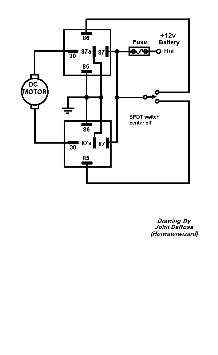
Yep..I count "5" on each.. lol Nice diagram. -------------
Posted By: hotwaterwizard
Date Posted: October 28, 2006 at 1:27 AM
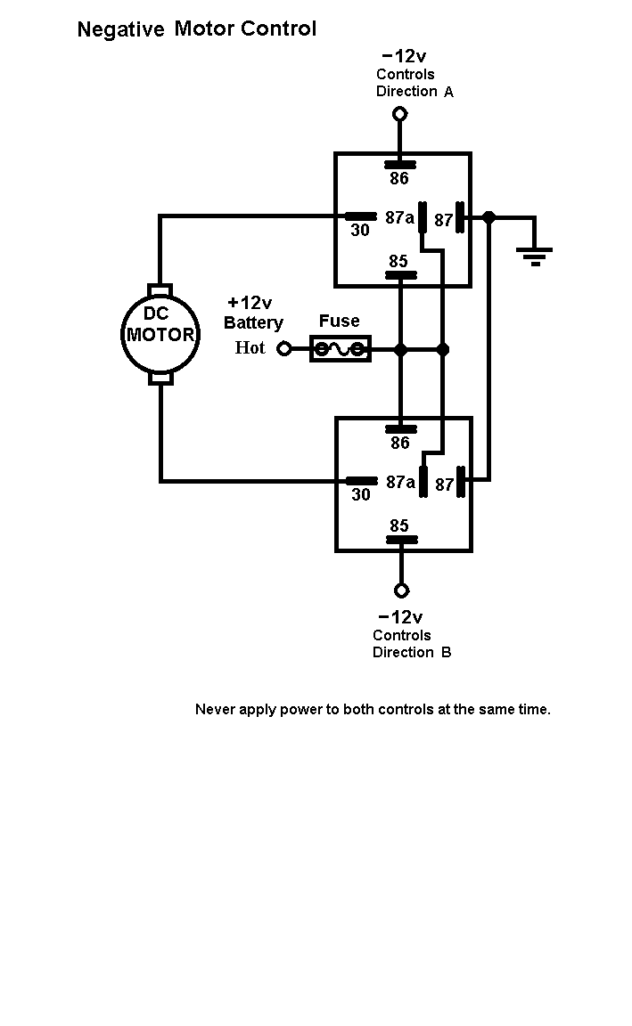
All of them are used too! I count 10 on the relays combined. If I had more fingers I could count even higher!  ------------- John DeRosa (Hotwaterwizard)
Stockton California
When in doubt, try it out !
Posted By: hotwaterwizard
Date Posted: October 28, 2006 at 1:49 AM
 ------------- John DeRosa (Hotwaterwizard)
Stockton California
When in doubt, try it out !
Posted By: hotwaterwizard
Date Posted: October 28, 2006 at 1:49 AM
 ------------- John DeRosa (Hotwaterwizard)
Stockton California
When in doubt, try it out !
Posted By: master5
Date Posted: October 28, 2006 at 11:37 AM
Excellent, you showed several ways to do this. Most likely the negative control will be used but many systems put out both on the doorlock outputs so either may work, Although there would be no point to applying power to both controls, and the system itself , and any switches used if functioning properly would not do this, it actually wouldn't do any harm. It would simply send 12+ to both legs of the actuator and no current would flow, similar but the opposite of what it is doing in its "at rest" state, each leg is recieving 12- with no harm. (or vice-versa), it just wouldn't operate the actuator. In the 3rd diagram (negative control motor) although this would work, IMO I prefer to not ever have the legs rest at 12v positive since these run from the relays, through the door jams, into the doors. Too many risks of a short to ground. (blown fuses or worse if installed improperly) In addition, any manual switch(es) installed to operate the locks as well, can be negative, hence less running of "live" 12v +power throughout the vehicle. I would prefer to use diagram 1. As long as one side of the relay coils are on 12+ constant, a negative on the other will activate the relay. -------------
Posted By: BLT79
Date Posted: November 04, 2006 at 1:01 PM
ok I get this diagram for 1 actuator, but how would you wire 2 relays for 2 actuators?
Posted By: hotwaterwizard
Date Posted: November 04, 2006 at 3:30 PM
Doing the same thing you just put the Actuators across eachother in Parallel. Like you would a speaker Positve to Positive Negitive to Negitive.
-------------
John DeRosa (Hotwaterwizard)
Stockton California
When in doubt, try it out !
|


