Latched relay?
Printed From: the12volt.com
Forum Name: Relays
Forum Discription: Relay Diagrams, SPDT Relays, SPST Relays, DPDT Relays, Latching Relays, etc.
URL: https://www.the12volt.com/installbay/forum_posts.asp?tid=86504
Printed Date: May 13, 2026 at 4:05 PM
Topic: Latched relay?
Posted By: ricey777
Subject: Latched relay?
Date Posted: December 01, 2006 at 4:14 PM
Great site !!
I am having problems with my central locking on my VW Golf. Here is a diagram.
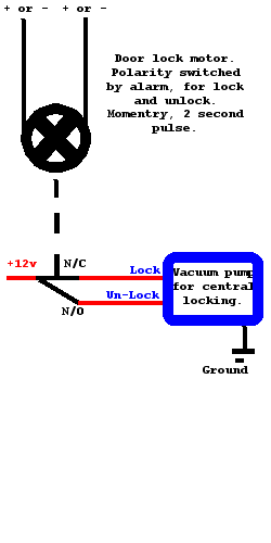
It is a vacuum pump type system, which i have added a door lock motor triggered by my alarm system. The alarm supplies +12v, reversing the polarity to lock and unlock. The motor is connected to a switch, via a short piece of metal rod, which is also connected to the door lock by another piece of rod. This permanently switches 12v to the vacuum pump at 2 different terminals for lock and unlock.
The problem is with the connection between the motor and switch, and is a little hit and miss.
I would like to replace the switching part of the system with a relay setup, so hopefully giving a trouble free system.
Any suggestions?
Replies:
Posted By: hotwaterwizard
Date Posted: December 01, 2006 at 7:52 PM
A few more details about the switch would help. ] As I understand it you want a Relay to flip the motor wires from positive to negitive and rest then switch from negitive to positive then rest whenever a pulse is put on lock or unlock. ------------- John DeRosa (Hotwaterwizard)
Stockton California
When in doubt, try it out !
Posted By: master5
Date Posted: December 01, 2006 at 8:14 PM
By "hit or miss" do you mean the switch has a problem? or the vaccum? You didn't mention the year but I used to do alot of these type locks on the older benzes..looks very similar. The problems i would find usually lead to the vacuum lines dried out and leaking so they were not consistant. Normally the "switch" is the doorlock itself..does this vehicle have a regular toggle somewhere or only works off the doors (central locking) If the problem is the switch..you may need a new one. The best bet on those older ones is to replace all the vacuum locks for electric actuators..you can even use a central locking system which allows the front door locks to control the rears...as well as using your keyless entry. Post back if you have more info..I don't fully understand the problem. -------------
Posted By: ricey777
Date Posted: December 01, 2006 at 8:41 PM
What i want to do is replace the toggle switch that powers the vacuum pump. It seems the door lock motor has a shorter stroke than the toggle switch, so sometimes it doesn't unlock.
My idea was to keep the door lock motor to lock the drivers door, and to have the alarm pulse signal to switch the vacuum pump via a relay set up.
The alarm puts out a pulsed +12v but it isnt long enough to drive the vacuum pump. The vacuum pump has two 12v inputs, 1 to lock and 1 to unlock. When the central locking system was standard the 12v to either of these inputs is permanent, switched by the toggle switch in the door.
Posted By: hotwaterwizard
Date Posted: December 01, 2006 at 9:00 PM
 ------------- John DeRosa (Hotwaterwizard)
Stockton California
When in doubt, try it out !
Posted By: ricey777
Date Posted: December 01, 2006 at 9:27 PM
I do not want any switches !!!
I want the momentry pulse from the alarm to switch the vacuum pump via relay.
Posted By: hotwaterwizard
Date Posted: December 01, 2006 at 9:48 PM
 ------------- John DeRosa (Hotwaterwizard)
Stockton California
When in doubt, try it out !
Posted By: master5
Date Posted: December 01, 2006 at 9:53 PM
I think I finally understand this. It would help to know the year of the car but if it's an older vacuum locks it requires an extended pulse to operate properly..a relay will not fix this. You need to check the programming menu of your security system to see if it has a feature to extend the doorlock pulse. If you don't have a menu (should be in the installation manual) post the make and model of the alarm and maybe we can get the info. If your unit is not programmable for this they sell pulse extenders for this very purpose. They are cheap so it's worth it rather then building your own..which is another option. -------------
Posted By: hotwaterwizard
Date Posted: December 01, 2006 at 9:57 PM
 ------------- John DeRosa (Hotwaterwizard)
Stockton California
When in doubt, try it out !
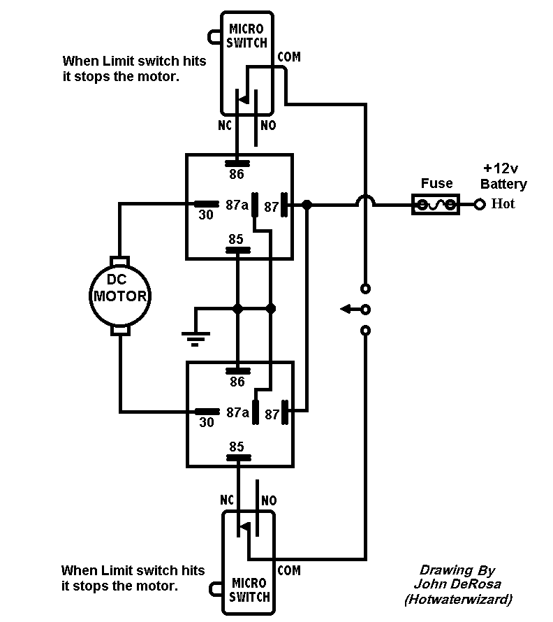
Posted By: hotwaterwizard
Date Posted: December 01, 2006 at 9:59 PM
The timing cycle on this circuit is the same as the previous. 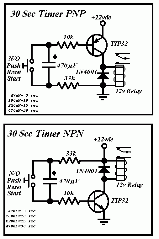
------------- John DeRosa (Hotwaterwizard)
Stockton California
When in doubt, try it out !
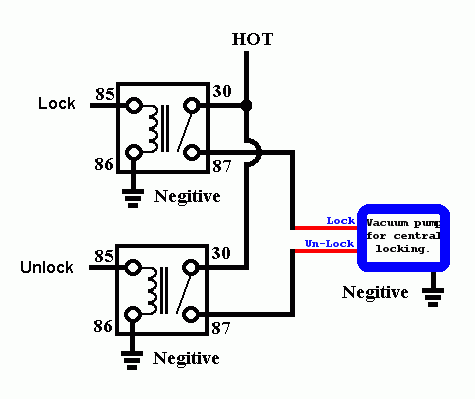
Posted By: master5
Date Posted: December 01, 2006 at 10:08 PM
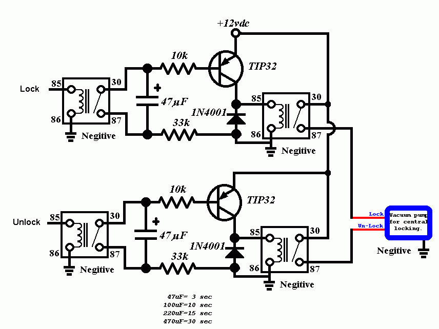
Oh wait....lol....now I get it....ok..your diagram shows rest at 12v+..... N/C for lock..N/O for unlock...wire it like this...Do we have a winner??? 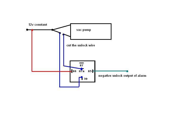
-------------
Posted By: master5
Date Posted: December 01, 2006 at 10:23 PM
If that doesn't work..put the wire that is on 87a to 87..Its been like 10 years since I have done this..but I know it will work..you just need to get the relay to simulate what the switch does...the older benzes that I was confusing this system with requires the extended pulse if doing the locks at the pump. Since you are using the factory switch at the door via an electronic actuator..and your problem seems to be it doesn't fully engage the switch for unlock...this will work. Sorry for all the confusion..you gotta laugh.
-------------
Posted By: master5
Date Posted: December 01, 2006 at 10:30 PM
Wizard...man you are the diagram wizard..amazing.The only thing is..and I should have stated this earlier..is if it did require the extended pulse..it would only need about 3 seconds max...just long enough for the pump to cycle long enough to lock and unlock..30 seconds is way overkill. But since in this case we are at the switch in the door that controls the module ..we do not need the delay.
-------------
Posted By: hotwaterwizard
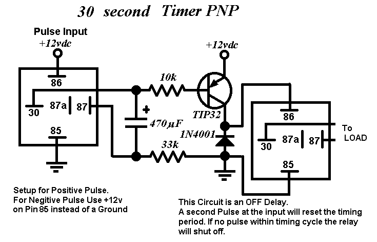
Date Posted: December 01, 2006 at 11:26 PM
Did you look at the other Diagram? Just use a 47uF Capacitor instead of a 470uF. ------------- John DeRosa (Hotwaterwizard)
Stockton California
When in doubt, try it out !
Posted By: hotwaterwizard
Date Posted: December 01, 2006 at 11:31 PM
 ------------- John DeRosa (Hotwaterwizard)
Stockton California
When in doubt, try it out !
Posted By: KPierson
Date Posted: December 02, 2006 at 12:12 AM
Are you sure that diagram will work? Where is your voltage differential that charges the cap? Looks like both sides of it will go to ground. ------------- Kevin Pierson
Posted By: hotwaterwizard
Date Posted: December 02, 2006 at 12:26 AM
Yes this one works. The Transistor provides the voltage until saturation is achieved. The capacitor charges at a RC time set by the components. The capacitor starts charging when you short it out and release. When the capacitor gets to a full charge it turns off the second relay . When in doubt, try it out ! When in doubt, try it out ! ------------- John DeRosa (Hotwaterwizard)
Stockton California
When in doubt, try it out !
Posted By: KPierson
Date Posted: December 02, 2006 at 12:31 AM
Where is the voltage supplied from that charges the cap? From the top of the emitter back through the base? Also, how is the cap discharging going to keep a PNP transistor biased? ------------- Kevin Pierson
Posted By: hotwaterwizard
Date Posted: December 02, 2006 at 12:34 AM
This is the Original circuit that I modified. Trust me it works. ------------- John DeRosa (Hotwaterwizard)
Stockton California
When in doubt, try it out !
Posted By: KPierson
Date Posted: December 02, 2006 at 1:03 AM
OK, a little time with my 'scope and I see now. I built the NPN version, using a 30K resistor, a 10K resistor, a 2n3904, and a 68uF electrolytic cap. The two resistors in series form a voltage divider, making the base of the transistor more negative then the power supply. When you short out the cap it discharges, and as the cap charges back up it allows voltage to pass through it. Once the cap is full, it 'opens' and no more current flows. I never would have thought to do it that way. Hmmm... you know you are getting older when you don't have anything better to do at 2AM on a Friday night then learn how a new circuit works...... ------------- Kevin Pierson
Posted By: ricey777
Date Posted: December 02, 2006 at 6:04 AM
hotwaterwizard wrote:
Thats It !!
Can i not just put a cap across each coil to delay the release?
3 or 4 seconds will be ample.
Posted By: hotwaterwizard
Date Posted: December 02, 2006 at 10:23 AM
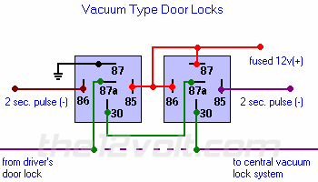
I found this in the Special Applications Relay section of this site. https://www.the12volt.com/doorlocks/doorlocks.asp Found mostly on Mercedes Benz vehicles, the movement of the door lock actuators is controlled by a central vacuum pump. The switch changes polarity on a single wire that may rest at power or ground depending on the state of the door locks. You can duplicate this with at least a 2 second pulse. If the alarm or keyless entry you are installing does not have a 2 second or longer duration option for the door lock outputs, do not use this diagram (it will not work unless you incorporate a timer into this circuit).
------------- John DeRosa (Hotwaterwizard)
Stockton California
When in doubt, try it out !
Posted By: hotwaterwizard
Date Posted: December 02, 2006 at 10:42 AM
Like this? 
A very large capacitor would do the trick. ------------- John DeRosa (Hotwaterwizard)
Stockton California
When in doubt, try it out !
Posted By: ricey777
Date Posted: December 02, 2006 at 10:46 AM
The alrm output is a very short pulse, probably one second. The central locking pump however requires around 3 seconds to lock or unlock the doors. In the original set up the 12v is constant to the lock or unlock wires.
Posted By: ricey777
Date Posted: December 02, 2006 at 10:48 AM
Yes that looks good.
What value cap though ?
Posted By: ricey777
Date Posted: December 02, 2006 at 11:03 AM
OK.
If my relay has a resistance of 80 ohms, a cap of 50,000uF will give a delay of 4 seconds ?
Posted By: hotwaterwizard
Date Posted: December 02, 2006 at 11:10 AM
 ------------- John DeRosa (Hotwaterwizard)
Stockton California
When in doubt, try it out !
Posted By: ricey777
Date Posted: December 02, 2006 at 11:21 AM
Why the extra components, when i can do it with 2 relays, 2 caps and 2 diodes ???
Posted By: hotwaterwizard
Date Posted: December 02, 2006 at 11:23 AM
50,000 uF Capacitors are Available. Datasheet in PDF Format
https://www.vishay.com/docs/42066/36ddedx.pdf Available at Mouser about $14 each
https://www.mouser.com/search/ProductDetail.aspx?R=36DX503G025CC2Avirtualkey61320000virtualkey75-36DX503G025CC2A physical size each
2.5 inches x 4.125 inches Almost the size of a Soda can each. ------------- John DeRosa (Hotwaterwizard)
Stockton California
When in doubt, try it out !
Posted By: ricey777
Date Posted: December 02, 2006 at 11:34 AM
can you have a look at these ?
LINK
They are quite small 2" x 1.5".
Are they OK ??
Posted By: hotwaterwizard
Date Posted: December 02, 2006 at 11:38 AM
The picture does not match the words. And the Voltage is real close to your actual voltage. They should be okay. The ones I posted are Computer Grade Rated at 25v ------------- John DeRosa (Hotwaterwizard)
Stockton California
When in doubt, try it out !
Posted By: master5
Date Posted: December 02, 2006 at 11:48 AM
I was under the impression that the problem is the actuator you put in the door does not have enough throw for the switch. If this is the case why are you messing with the timing...or capacitors? -------------
Posted By: ricey777
Date Posted: December 02, 2006 at 11:52 AM
I want to get rid of the mechanical switch and replicate it with relays. Less hassle !!
Posted By: master5
Date Posted: December 02, 2006 at 12:17 PM
let me know the year of the car.
-------------
Posted By: ricey777
Date Posted: December 02, 2006 at 12:30 PM
master5 wrote:
let me know the year of the car.
1990 VW Golf (Rabbit in US?) GTI
|