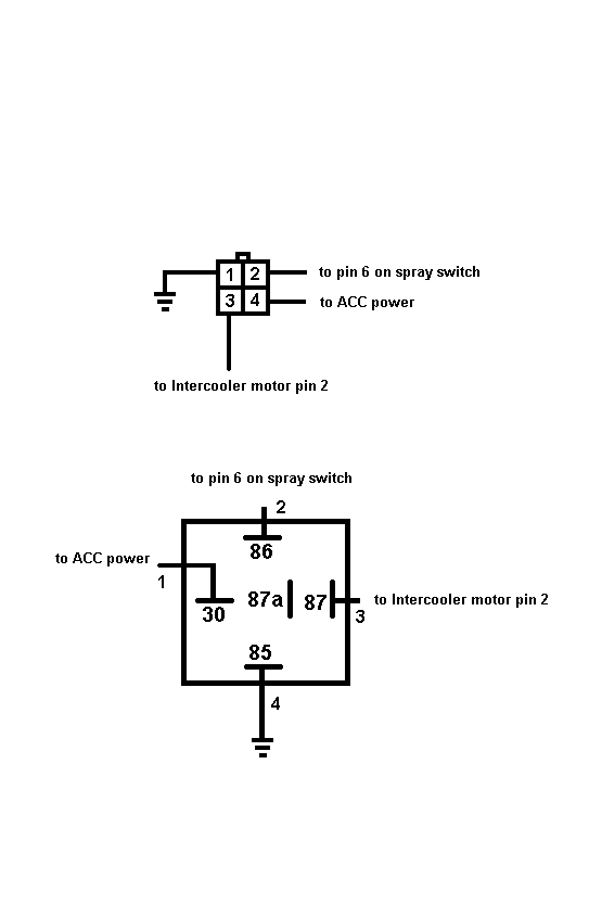
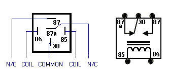
Intercooler Sprayer Wiring
Printed From: the12volt.com
Forum Name: Relays
Forum Discription: Relay Diagrams, SPDT Relays, SPST Relays, DPDT Relays, Latching Relays, etc.
URL: https://www.the12volt.com/installbay/forum_posts.asp?tid=87370
Printed Date: February 04, 2026 at 1:32 AM
Topic: Intercooler Sprayer Wiring
Posted By: aboothman
Subject: Intercooler Sprayer Wiring
Date Posted: December 17, 2006 at 8:13 PM
OK, so here is my situation. I am installing an Intercooler Sprayer setup in my 06 Subaru WRX.
Here is the stock IC sprayer scematic from a STI:
Stock IC Sprayer Scematic
Here is the scematic I used for my setup.
Auto Spray switch and Boost Pressure switch added
I do not have the factory IC Spray timer.
It appears that it is a switched negative circuit, but I could be wrong. My first scematic below is what I came up with from all the searching I have done on the topic.
I have all the parts ready, and I have a couple wiring scematics to go by. However, they do not work. Here are the two scematics that I have:
Scematic #1
Scematic #2
Both circuits make use of a parallel design using 2 switches: First is a momentary switch that sprays as long as I hold it down. I will eventually find an adjustable timer, so if you have any leads on something that will work I would appreciate it.
The second switch is an on/off switch, and arms the boost pressure switch that is installed in my boost gauge vacuum line.
In my limited experience, my issue with the first scematic is the lack of a ground on the relay. I dunno if this is a problem.
I am also curious if the relay will be a power drain on my battery since it will be directly connected.
I have tried both scematics, and neither works. I have checked all fuses, connectors, ect. I am currently using the multimeter to make sure everything is what my reference scematics say it is.
Thanks for any help.
Replies:
Posted By: aboothman
Date Posted: December 17, 2006 at 8:42 PM
bad links for scematics 1 and 2. Updated:
Scematic #1
Scematic #2
Posted By: hotwaterwizard
Date Posted: December 19, 2006 at 9:16 AM
It looks like you can use a standard Relay until you find your timer. 
------------- John DeRosa (Hotwaterwizard)
Stockton California
When in doubt, try it out !
Posted By: aboothman
Date Posted: December 19, 2006 at 8:41 PM
I should fix my original pics, and add another that shows the back of the switch:
My Scematic #1

My Scematic #2

Switch Pin Out

Posted By: aboothman
Date Posted: December 19, 2006 at 8:43 PM
Wish I could edit my posts here....
anyway, I forgot to ask how I can determine what pins do what on the switch?
I KNOW that pin 2 and 4 are correct, but there are many other opinions on what the others do.
Posted By: hotwaterwizard
Date Posted: December 19, 2006 at 10:29 PM
Pin 85 is a ground not a hot. It will not work with hot on both sides of the coil of the relay.
-------------
John DeRosa (Hotwaterwizard)
Stockton California
When in doubt, try it out !
Posted By: aboothman
Date Posted: December 19, 2006 at 10:32 PM
ok I got it fully figured out now. Thanks for your help!!
If hindsight it was so blatently simple I am embarassed.
Posted By: hotwaterwizard
Date Posted: December 19, 2006 at 10:36 PM
Are you sure you got it? 
------------- John DeRosa (Hotwaterwizard)
Stockton California
When in doubt, try it out !
Posted By: aboothman
Date Posted: December 19, 2006 at 10:44 PM
latest version:

Posted By: hotwaterwizard
Date Posted: December 19, 2006 at 10:50 PM
This switch? Is it a slider switch a 3 way switch ? Want more info on it
-------------
John DeRosa (Hotwaterwizard)
Stockton California
When in doubt, try it out !
Posted By: aboothman
Date Posted: December 19, 2006 at 11:03 PM
The switch labeled Instercooler Spray Switch is a momentary pushbutton switch.
The switch labeled JDM Spray Switch is an on/off pushbutton switch. Its purpose is to activate the Boost Pressure Switch, and operate in parallel with the momentary switch.
Pins 2 and 4 are for illumination, and tap into the approiate wires from the Fog Light Switch...which occupies a space right next to the mounting location of the added switches.
I guess that the only ground needed on the switches is for the illumination.
Posted By: hotwaterwizard
Date Posted: December 19, 2006 at 11:05 PM
Look at this! sti automatic intercooler spray switch https://forums.nasioc.com/forums/showthread.php?t=963893 ------------- John DeRosa (Hotwaterwizard)
Stockton California
When in doubt, try it out !
Posted By: aboothman
Date Posted: December 20, 2006 at 1:07 AM
ya lol, he actually helped me going it going tonight. I have read every thread possible, but there was a slight difference with my setup as I was not going to use the factory timer.
However, it appears the factory timer is setup exactly how a relay would be. I assume the timer IS a relay.
So now, my plan is to get an alarm relay with an adjustable timer and use it as my relay.
|


