trying to control linear actuators
Printed From: the12volt.com
Forum Name: Relays
Forum Discription: Relay Diagrams, SPDT Relays, SPST Relays, DPDT Relays, Latching Relays, etc.
URL: https://www.the12volt.com/installbay/forum_posts.asp?tid=90977
Printed Date: May 07, 2026 at 7:25 PM
Topic: trying to control linear actuators
Posted By: 6linkslam
Subject: trying to control linear actuators
Date Posted: February 25, 2007 at 6:51 PM
i am going to make a tonneau cover lift and i am wondering what would be the best thing to use to control it. i have a 12 channel keyless entry from electric-life and linear actuators. what can i use to be able to press the button on my remote one time and have the actuators stop at the right time for open and close? i was wondering if the dei 528t pulse timer relay would work or a dei 611t. also im going to use an actuator for each side. any help would be greatly appreciated. hopefully i have explained enough about what i need.
Replies:
Posted By: hotwaterwizard
Date Posted: February 25, 2007 at 7:47 PM
You could use Micro switches or a timer. But first you need a couple of Relays. 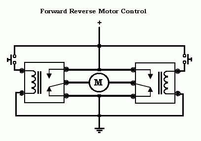
------------- John DeRosa (Hotwaterwizard)
Stockton California
When in doubt, try it out !
Posted By: 6linkslam
Date Posted: February 25, 2007 at 7:58 PM
i dont fully understand what the diagram is showing me couls you please be a lil more specific. thanks
Posted By: hotwaterwizard
Date Posted: February 25, 2007 at 8:05 PM
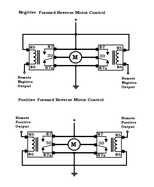
The Relays flip the polarity so it can go up and down with your remote.
-------------
John DeRosa (Hotwaterwizard)
Stockton California
When in doubt, try it out !
Posted By: hotwaterwizard
Date Posted: February 25, 2007 at 8:09 PM
M is the Actuator Motor that has wires to control it. If you put 12v on the wires it will go either up or down. Switch the wires around and it goes the other way.
-------------
John DeRosa (Hotwaterwizard)
Stockton California
When in doubt, try it out !
Posted By: 6linkslam
Date Posted: February 25, 2007 at 8:37 PM
what can i use to make this an automatic process. example: press button on remote one time and the cover goes up until it gets to where i want it to stop then press another button and the cover closes but does not keep going until damage occours to the cover or brackets that attach it. this is why i was wondering about using a timer so i can program a run time for open and close.
Posted By: hotwaterwizard
Date Posted: February 25, 2007 at 9:32 PM
You need Micro switches and a Latching input on each side. Or some Pin switches and micro switches. 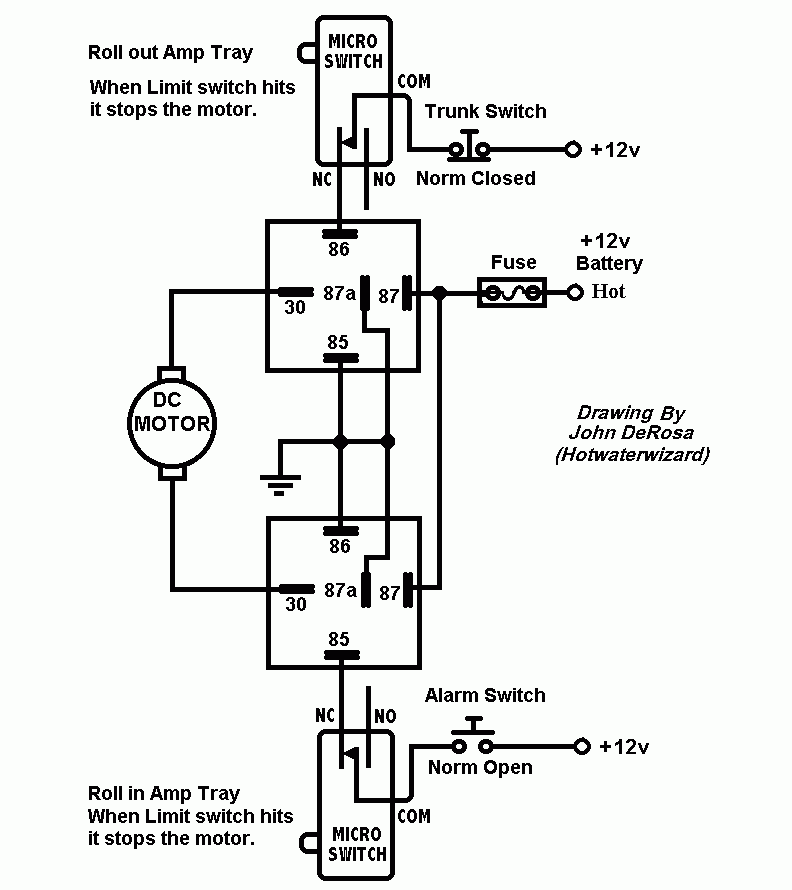
------------- John DeRosa (Hotwaterwizard)
Stockton California
When in doubt, try it out !
Posted By: 6linkslam
Date Posted: February 25, 2007 at 10:17 PM
so would the dei 528t be an option or not?
Posted By: hotwaterwizard
Date Posted: February 26, 2007 at 7:44 AM
I think the dei528 would make it go up and anoyher would be needed to make it go down. The wiring of this is not familar to me because I have never had one in my hand to experiment with. ------------- John DeRosa (Hotwaterwizard)
Stockton California
When in doubt, try it out !
Posted By: hotwaterwizard
Date Posted: February 26, 2007 at 8:21 AM
Posted By: tommyhawk
Date Posted: March 09, 2007 at 4:42 PM
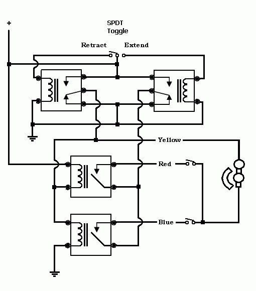
Hi - So, looking at your larger diagram, is the "Alarm Switch (NO)" a momentary switch? If not, will this setup work with a momentary switch in that position? I'm working on a project much like a CD drive: push the button once, the mechanism travels to its limits in one direction and stops, push the botton again and it travels to the limit in the other direction. Thanks!
Posted By: hotwaterwizard
Date Posted: March 09, 2007 at 10:06 PM
It is a pin switch. Yes a momentary will work if you want to operate it by hand. ------------- John DeRosa (Hotwaterwizard)
Stockton California
When in doubt, try it out !
Posted By: tommyhawk
Date Posted: March 12, 2007 at 8:47 AM
Great, thanks. Your diagrams in this actuator thread, and several others, are terrific. Thanks for laying it all out.
Posted By: tommyhawk
Date Posted: March 12, 2007 at 2:12 PM
If I may - I have two questions about the relays in your diagram. - Are these (should they be) DPDT? - What amperage would you suggest they handle, would 15 amps be ok? Thanks again.
Posted By: hotwaterwizard
Date Posted: March 12, 2007 at 7:50 PM
SPDT Automotive Relays rated at 30 amps https://www.the12volt.com/relays/relays.asp 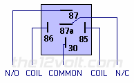  
------------- John DeRosa (Hotwaterwizard)
Stockton California
When in doubt, try it out !
Posted By: tommyhawk
Date Posted: March 14, 2007 at 11:36 AM
Right, right. I've read the tutorials, but got confused in looking at other projects. SPDT @ 30 amps, thanks. Could you provide some guidance on the limit switches? How many amps do they need to handle, and got any suggestions for a product?
Posted By: hotwaterwizard
Date Posted: March 14, 2007 at 8:27 PM
If the limit switches control the relay, Less than 1 amp. If they control the Actuator motor that depends on the Amp draw of the Actuator. ------------- John DeRosa (Hotwaterwizard)
Stockton California
When in doubt, try it out !
Posted By: tommyhawk
Date Posted: March 16, 2007 at 1:48 PM
Thanks. Pouring over this some more - if I put a momentary switch in that Alarm Switch position, would that not just cause the coils on the relays to energize only for a second, thus the actuator would only run for that brief instant? I mean, using this setup as it stands, do I have to hold the button down until it reaches the opposite limit switch? Ideally, I'd like to touch (and release) my button once and have the actuator run its full length until it reaches the opposite limit switch. Touch it again, it reverses, like a DVD drive. Perhaps I'd need latching relays?
Posted By: tommyhawk
Date Posted: March 16, 2007 at 2:08 PM
Continued from above... my parts aren't here yet so I've nothing to do except try to think this through... Initially the actuator will be sitting against one limit switch or the other, that switch will be Open, so that relay coil won't be energized. I hit my button... Maybe my problem is that you included a Trunk Switch (cool idea). As it stands, am I correct saying that if I eliminate the Trunk switch, I have no way to reverse the actuator?
Posted By: tommyhawk
Date Posted: March 16, 2007 at 2:53 PM
Or even better, I'm trying to understand how to throw the "momentary to constant" diagram into this mix: https://www.the12volt.com/relays/page5.asp#mtc Could you slam this into your diagram?
Posted By: dualsport
Date Posted: April 06, 2007 at 12:59 PM
Try this modification to Hotwater's circuit to use a single switch for a latching up/down configuration.  This assumes the microswitch is set up to be in the Normally Open position when the limit is reached, and NC otherwise. changed the ground control for the relays to use the opposing side relay to prevent a situation where both relays can get energized if the control is hit while already moving, stopping the motor from traveling to the limits.
Posted By: hotwaterwizard
Date Posted: April 07, 2007 at 2:29 AM
 ------------- John DeRosa (Hotwaterwizard)
Stockton California
When in doubt, try it out !
Posted By: tommyhawk
Date Posted: April 09, 2007 at 9:48 AM
Perfect! These new diagrams are exactly what I'm needing. I received my parts and have cobbled this together in "test mode", but couldn't quite make it operate like I need it to. I'll get out and buy two diodes right away (I was close to doing that anyway, based on the other tutorials, not that I knew exactly what to do with them). I'll let you know how it goes. Great forum here! You guys are very helpful and I appreciate your input.
Posted By: tommyhawk
Date Posted: April 09, 2007 at 10:20 AM
One clarification: I am to wire the blocked end of the diode to the COM terminal of the micro switch, not to the NC terminal, yes? Just so I'm sure.
Posted By: dualsport
Date Posted: April 09, 2007 at 7:14 PM
Yes, the diodes should be connected to the COM of the microswitches.
The purpose of the diode is to provide a latching function, keeping the relay energized until the limit switch is hit, and opens up the connection, turning the relay power off, until you push the switch again. A run of the mill 1N4001 diode should do for this application.
Without a diode to block the current in the reverse direction, the control voltage would get shorted to ground. So, make sure you get the polarity of the diode correct-
|