reverse polarity with a twist.
Printed From: the12volt.com
Forum Name: Relays
Forum Discription: Relay Diagrams, SPDT Relays, SPST Relays, DPDT Relays, Latching Relays, etc.
URL: https://www.the12volt.com/installbay/forum_posts.asp?tid=91451
Printed Date: March 20, 2026 at 7:07 PM
Topic: reverse polarity with a twist.
Posted By: hyperryd
Subject: reverse polarity with a twist.
Date Posted: March 08, 2007 at 11:58 PM
OK, I have searched around and I can't find what I am looking for so here is my question. I have a switch that puts a negative feed out on a wire on the down position and then a positive feed out in the up position on the same wire. I want two different positive feeds to power two different electric valves. There is no way to rewire the switch as it is a sealed switch that I dont want to mess with the internals. Wiring a relay to convert the negative over to positive is no problem. The problem is I have split the wire with one side going directly to the valve and the other wire going to the negative side of the reversing relay. The wire going to the relay is getting negative feedback from the other leg going to the valve, which charges the relay all the time. If I use a diode on the valve leg, to stop the negative feedback, positive flow is stopped from going to the valve. If I use a diode on the relay leg, negative flow is stopped so the negative signal from the switch is lost. I have tried so many relay and diode configurations and all I have is a headache. I know this is possible, but I have hit a mental wall. I know I am staring right at the solution, but I can't see the forest through all of the trees. I'm not sure if a resistor would help here and I am resistor illiterate. Any help would be appreciated
Replies:
Posted By: frydchkn
Date Posted: March 09, 2007 at 12:35 AM
How about permanently grounding one valve, with a positive trigger from the switch. And have the other valve with constant power, but with a negative trigger from the switch. -no need for relays. What are the valves controlling? just curious
Posted By: hyperryd
Date Posted: March 09, 2007 at 6:42 AM
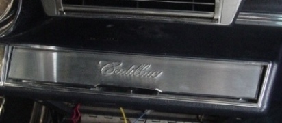
You know I was laying in bed last night thinking the same thing, but thinking that I might still get feedback that would be enough to trigger the other valve, but I will try it later today when I get off of work just to see. These are airbag valves to lay out a 1965 Cadillac using a 1965 6-way power seat switch. My friend doesn't want any modern switches in the interior.
Posted By: hyperryd
Date Posted: March 09, 2007 at 6:47 PM
No, such luck. The coils on the valves feed back once one valve is activated and both valves stay open. This is really frustrating.
Posted By: hotwaterwizard
Date Posted: March 09, 2007 at 10:42 PM
 ------------- John DeRosa (Hotwaterwizard)
Stockton California
When in doubt, try it out !
Posted By: hyperryd
Date Posted: March 09, 2007 at 10:53 PM
The problem is if I activate valve number two the negative crosses the coil and energizes valve number one, and visa versa. Great diagram for my switch though. Thanks.
Posted By: hotwaterwizard
Date Posted: March 09, 2007 at 11:59 PM
Just add a couple of General Purpose Diodes. 
------------- John DeRosa (Hotwaterwizard)
Stockton California
When in doubt, try it out !
Posted By: dualsport
Date Posted: March 09, 2007 at 11:59 PM
Here's a possible circuit you can try-

It uses two zener diodes to block the current path from 12V to ground, (assuming your switching signal is open circuit when off, and either 12V or ground when you hit the switch.
The transistors amplify the current signal to switch the relays and give you the two (+) outputs. If you don't need much current you could do without the K1 relay and just use the output of the transistor. You might need to diddle with the resistance values and select the appropriate transistor part depending on the relay or signal input that you're planning on driving with it.
Posted By: hotwaterwizard
Date Posted: March 10, 2007 at 12:03 AM
Keep it simple. Try the Diodes. Trust me it will work.
-------------
John DeRosa (Hotwaterwizard)
Stockton California
When in doubt, try it out !
Posted By: dualsport
Date Posted: March 10, 2007 at 12:09 AM
The problem is the diodes are not back to back in the series chain, so current will be constantly flowing through them, and the valves.
If this is for a car application, it'll be a drain on the battery, assuming the valves won't remain switched on with 1/2 battery voltage.
The drop out voltage of the valves might be low enough that the valves will remain on once they're energized.
How much current do the valves need to operate? If it's fairly high, you really need to use relays; or some hefty diodes, since they'd need to pass all the current needed by the valves.
Posted By: hyperryd
Date Posted: March 10, 2007 at 12:15 AM
I kept trying diodes and relays on the signal wire not the supply wire. I will try that . I really like simple if it will work. Thanks for the replies guys. I will keep you posted.
Posted By: hotwaterwizard
Date Posted: March 10, 2007 at 12:15 AM
OOPS Here is the correct Diagram 
------------- John DeRosa (Hotwaterwizard)
Stockton California
When in doubt, try it out !
Posted By: hyperryd
Date Posted: March 10, 2007 at 12:25 AM
I guess we are all posting at the same time. 1. The valves use a light coil basically like a relay to activate them so they are very sensative. 2. If I use the diode on the the signal wires the way pictured, they don't stop any signals from feeding back. On the valve twp leg, the diode will stop posative feedback, but not negative feedback. Or am I just looking at that wrong? I'm pretty sure that was the first configuration I tried, but I have tried a lot. I think the biggest problem is the relays and valve coils are so sensative that the minute feedback is setting everything off.
Posted By: hotwaterwizard
Date Posted: March 10, 2007 at 12:29 AM
I thought about that too so I posted another diagram. We were posting at the same time several times.
-------------
John DeRosa (Hotwaterwizard)
Stockton California
When in doubt, try it out !
Posted By: dualsport
Date Posted: March 10, 2007 at 12:34 AM
This is the equivalent circuit if only diodes are used-
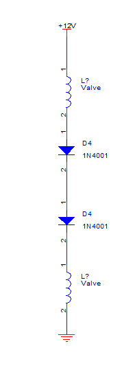
With the switch off, you have pretty much 1/2 the battery voltage across each of the valves, minus the bit of drop from the diodes. Relays generally have a lower turn off voltage than the turn on voltage, so that's probably why you noticed them staying on once they got energized.
Simplest might be to stick in another switch; nothing gets much simpler than a mechanical toggle switch.
Posted By: hotwaterwizard
Date Posted: March 10, 2007 at 12:35 AM
Ok lets find another solution
-------------
John DeRosa (Hotwaterwizard)
Stockton California
When in doubt, try it out !
Posted By: dualsport
Date Posted: March 10, 2007 at 12:41 AM
Adding a toggle switch is starting to look good now- 
Let's first make SURE the friend doesn't want to reconsider that option 
Posted By: hyperryd
Date Posted: March 10, 2007 at 12:43 AM
The extra switch issue is this. This is a 1965 Cadillac with front and back air bag suspension. My friend doesn't want a modern switchbox in the car. I found a 1965 Caddy power seat switch that matches the interior perfectly and fits in the ashtray like it came from the factory that way. So this is the switch we are talking about so I can't really add another swich. My general theory is if a switch puts out a signal there has to be a way to use that signal to activate a relay or coil of some sort. This one is challenging because of both polaritie on one wire, but my favorite saying is "If it was easy, everybody would do it." There has to be a way we just have to find it. I really do appreciate people who like a challenge as much as I do.
Posted By: hyperryd
Date Posted: March 10, 2007 at 12:48 AM
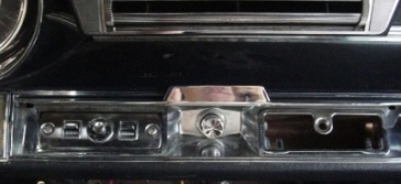
The other nice thing about the switch is there are two rockers switches to control the front and the rear that flank a joystick in the middle that will activate both switches up or down allowing him to control each end independantly with rocker or the whole car with the joystick. It would be a sweet set up, I just have to make it work.
Posted By: dualsport
Date Posted: March 10, 2007 at 12:52 AM
It really does seem like there should be an exceedingly simple solution to it, doesn't it- there's not much to it.
McGyver could probably work it with chewing gum, duct tape, and a rusty nail- should be interesting if someone finds the way.
Posted By: hyperryd
Date Posted: March 10, 2007 at 12:56 AM
The worst part is I know it will be a simple solution. I just don't know how much hair I will have when it is done. It's my fault for telling him how nice it would look and work before I had a switch to map out. I really figured it would have four ground at rest wires similar to a power window switch.
Posted By: dualsport
Date Posted: March 10, 2007 at 12:58 AM
The air suspension on my 95 Caddy has a switch mounted on the chassis to level it out to the same height independent of load; maybe that'd be something to rig up; no manual control needed, and the switch won't be visible, so you can use all manner of modern switches.
It isn't one of those setups where the car can hop up and down, but just a leveling setup right?
Posted By: hotwaterwizard
Date Posted: March 10, 2007 at 1:03 AM
Can you cut the wires?
-------------
John DeRosa (Hotwaterwizard)
Stockton California
When in doubt, try it out !
Posted By: hyperryd
Date Posted: March 10, 2007 at 1:04 AM
It's not for hopping, but it is for manual height adjustment. It is completely shaved and I wired up the exaust valves to his remote so that when he parks it he can lay it on the ground. It is really something to see as it is about 20 feet long and it looks about 40 feet long when it is layed out. This car is owned by a 40 year old who likes taking it to car shows and cruise nights.
Posted By: hyperryd
Date Posted: March 10, 2007 at 1:05 AM
Cut which wires?
Posted By: hotwaterwizard
Date Posted: March 10, 2007 at 1:06 AM
On the Switch
-------------
John DeRosa (Hotwaterwizard)
Stockton California
When in doubt, try it out !
Posted By: hyperryd
Date Posted: March 10, 2007 at 1:18 AM
Here is the breakdown on the switch. I should have done this earlier. There is power and ground going in and the one wire per switch coming out, along with two other wires that are a little uniqe as well. The orange wire is hot when any of the switches are up. The other wire is for the forward and back positions of the joystick that I am not using. The Orange wire might be the solution as a signal wire to some relays to isolate the up from the down signal. I tried that and ended up using the wires strait to the down valves and the up valves through two relays that interupted the up signal to the up valves. I used the orange wire to activate the relays to let the signal through when one up switch was activated. But again as soon as one up valve activated both valves ended up activating. I ended up with independant control of the front and rear down, but either up switch took the whole car up.
Posted By: hotwaterwizard
Date Posted: March 10, 2007 at 1:24 AM
 ------------- John DeRosa (Hotwaterwizard)
Stockton California
When in doubt, try it out !
Posted By: hotwaterwizard
Date Posted: March 10, 2007 at 1:30 AM
That is my solution just wire the switch the way you need it to work. All of the wires are used and it functions with no power drain. Gotta go to bed now. ------------- John DeRosa (Hotwaterwizard)
Stockton California
When in doubt, try it out !
Posted By: hyperryd
Date Posted: March 10, 2007 at 1:31 AM
We are close. The big problem is bothe switches have a common power and ground. This would only give one set of outputs instead of two.
Posted By: hyperryd
Date Posted: March 10, 2007 at 1:33 AM
Everybody sleep on it. Thanks for all of the discussion. It really gets the mind working. I will post back tomorrow with status.
Posted By: hotwaterwizard
Date Posted: March 10, 2007 at 1:35 AM
Draw a Diagram Please. How it is hooked yp now. You never mentioned 2 switches before ------------- John DeRosa (Hotwaterwizard)
Stockton California
When in doubt, try it out !
Posted By: dualsport
Date Posted: March 10, 2007 at 1:37 AM
Maybe you ought to reconsider opening up the switch to modify it for separate pwr/gnd inputZzzzzz 
Posted By: hotwaterwizard
Date Posted: March 10, 2007 at 1:40 AM
No need to open the switch we can deal with it.
-------------
John DeRosa (Hotwaterwizard)
Stockton California
When in doubt, try it out !
Posted By: hyperryd
Date Posted: March 10, 2007 at 1:42 AM
I really think your last diagram is the best by far and I think dualsports idea to reconfigure the internals of the switch to have separate pwr/grd will be the way to go. I will look at it in the morning and see how bad it would be.
Posted By: hyperryd
Date Posted: March 10, 2007 at 1:43 AM
Wizard, lets all think out it from the backside of our eyelids and check back tomorrow. Thanks guys.
Posted By: hyperryd
Date Posted: March 10, 2007 at 10:21 AM
I think I've got it going back to relays on the signal legs. I will post back after I try it. It seems too simple.
Posted By: djfearny2
Date Posted: March 10, 2007 at 11:44 AM
ok i dont completely understand what the heck is going on but to me it sounds like you have a switch that can throw both poss and negative up for pos down for neg or whatever but when you thro pos it feedbacks neg thru the line and vise versaumm i guess.
Have you tried reverse polarity on that signal wire.
meaning two relays on that one singal wire One for each switch with diodes. corespoding to the signal going to the relays
ok dont hate if i got your postings wrong and this was already discussed but i read and did not see it.
Switch
pos in
neg in
signal ( pos or neg)
take that signal wire and split it
relay 1
take one split and connect to pin 85 with a diode in order to make that a pos trigger relay. ( grey stripe facing away from relay)
take pin 87 make that your output to the valve.
pin 86 ground
pin 30 possitive 12 volts
87a not used
same for relay 2
take signal wire split connect it to pin 85 thru a diode with the strip facing the relay making this a negative trigger relay.,
pin 86 12 volt fused
pin 87 output to valve
pin 30 ground.
ok with the diodes and such in place the feedback should not be an issue becuase there is no way the valve can see that feeback since it is not connected the output wire of the valve does not see the input of relay unless it is supposed to .
Your main problem if it or this does not work is that the switch actually throws the opposite signal when you let go of it, Like if you push down you thro a negative signal., or whatever but when you let go of the down motion it automatically throws a possitive signal. if that is the case you cant use that as your switch and i would search for another factory looking switch.
hope this helps somewhat as i did not understand completely what your doing and such but post back,
-------------
Jon
Installer/Help Technician
---coral springs florida---
mecp certification is not always needed. I have it and it has not helped me out at all. my experience out shines it.
Posted By: hotwaterwizard
Date Posted: March 10, 2007 at 3:39 PM
Now I lost track of exactly what you want. The way I understand it you want to control 2 valves with 2 switches and make both valves do what the switch tells it to do wheather it is on the right door panel or left door panel. 
------------- John DeRosa (Hotwaterwizard)
Stockton California
When in doubt, try it out !
Posted By: hotwaterwizard
Date Posted: March 10, 2007 at 4:55 PM
2 switches controlling 2 valves. 
------------- John DeRosa (Hotwaterwizard)
Stockton California
When in doubt, try it out !
Posted By: hyperryd
Date Posted: March 10, 2007 at 7:00 PM
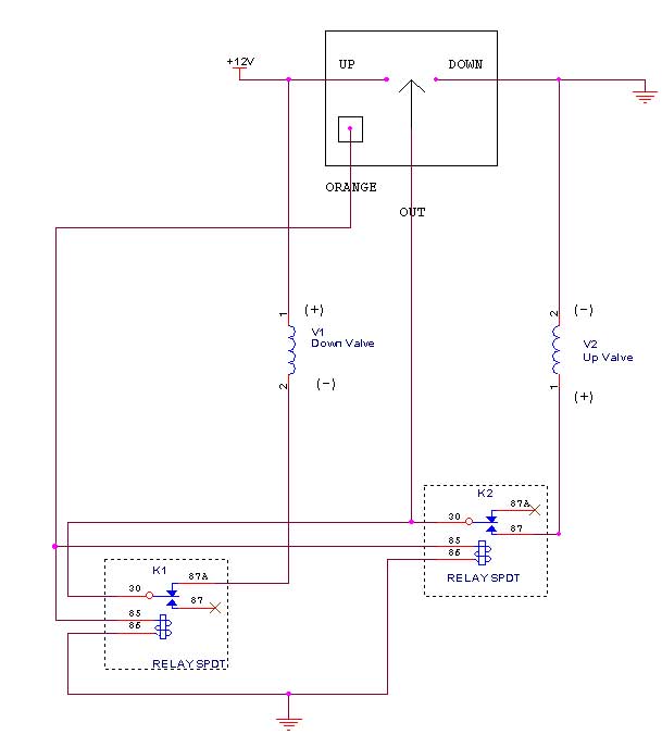
Wizard I hacked up your diagram and please realize I can't draw to save my life. This is the configuration that ended up working out. Valve 2 is down, valve 1 is up. The orange wire out of the switch is hot when any of the switches are up. When the switch is down the signal goes through the relay at rest to activate valve 2. The relay on valve one has the signal interupted at rest so there is no feedback. When the switch is up both valves energize from the orange wire letting the signal through to valve one and interupting valve two. I figured it out in the shower this morning, go figure. It works like a champ and the joystick works as well taking the whole car up or down with the joystick. Thanks for all of your help. I really feel that situations like this is where a discussion board is priceless. You can keep sounding ideas off of like minded people until someone finds the solution. 
Posted By: hyperryd
Date Posted: March 10, 2007 at 7:03 PM
By the way the diagram is for one of the rocker switches to control one end of the car. I did exactly the same thing for the other switch to control the other set of valves. There were four valves in all, controlled by two rocker switches that basically make the car go up or down like a power window switch.
Posted By: hotwaterwizard
Date Posted: March 10, 2007 at 7:07 PM
Great. Where did this orange wire come from. It would have been nice to have known about that before aswell as the application. Any time you need me just Email me hotwaterwizard@aol.com You can instant message me on AOL or AIM at my nickname hotwaterwizard ------------- John DeRosa (Hotwaterwizard)
Stockton California
When in doubt, try it out !
Posted By: hyperryd
Date Posted: March 10, 2007 at 7:47 PM
John, I think all of us were tired and skipping posts and posting at the same time last night. If you look back at the end of page 2, I described the switch set up and application and on the page 3 right before your diagram I described the extra two wires. Again I appreciate all of your help working through this. It works great and looks like it came from the factory in 1965.
Posted By: hotwaterwizard
Date Posted: March 10, 2007 at 10:00 PM
I fixed up the Drawing of your final design for you. Nice job. 
------------- John DeRosa (Hotwaterwizard)
Stockton California
When in doubt, try it out !
Posted By: dualsport
Date Posted: March 11, 2007 at 12:29 AM
I glossed over the orange wire too, but it doesn't matter, since you could have done the same thing with the use of the signal output to control the two relays- nice and simple, good going!
hotwaterwizard wrote:
I fixed up the Drawing of your final design for you. Nice job.
At first I thought the terminology of switch being 'up' meant off, or in the standby condition, but then realized up meant the pushing of the switch to command the suspension to go up.
If I have it straight, I think the connections for 87 and 87A connections should be reversed in the diagram- valve 1 (-) should go to 87A rather than 87, and valve 2 (+) should go to 87 rather than 87A.
And valve 2 should then be Up, valve 1 is Down.
Posted By: hyperryd
Date Posted: March 11, 2007 at 10:17 AM
The problem with using the signal wire to activate the valves it I still ended up with that feedback across the coil of the relays as well. As soon as you activated one relay the other one would energize at the same time. Using the orange wire eliminated that. I still don't understand why there was enough reverse polarity energy feeding back to activate the oposite coil so much, but sometimes you just have to work around a problem. As for the diagram, I don't deal with diagrams much, but I think it is right. When the switch is down the signal flows throught the 87a to the down valve. When any switch is up the orange wire is hot, which energizes both relays that disconnects valve 2 and lets the signal to open valve 1 through. It's amazing how when describing a problem to other people, when they can't see the situation, how hard it is to make sure that everybody understands the whole picture. Because I am looking at it, I take for granted that the other person knows what I am doing, and where I want it to go. There are times that I think I have given enough of a description, to solve the problem, but without being right there it is tough to grasp the little things that the person who is present sees. I do appreciate everybody's help though, it really helps get the mind going outside the box of the problem that you are staring blindly at when you have other educated opinions. I knew this could be done, but it was kicking my a**.
Posted By: dualsport
Date Posted: March 11, 2007 at 2:58 PM
Yeah, the separate orange wire is needed since the valve 1 would otherwise feed 12V to the relay coil K1 in the standby state.
This is what I figured you had worked out, with the NC and NO connections flipped.
Posted By: overworked2
Date Posted: March 27, 2007 at 2:58 PM
phew....I'm glad thats over!
-------------
Check all advice given with a meter
|