capacitor size for time delay
Printed From: the12volt.com
Forum Name: Relays
Forum Discription: Relay Diagrams, SPDT Relays, SPST Relays, DPDT Relays, Latching Relays, etc.
URL: https://www.the12volt.com/installbay/forum_posts.asp?tid=91691
Printed Date: February 20, 2026 at 11:32 PM
Topic: capacitor size for time delay
Posted By: whkoski
Subject: capacitor size for time delay
Date Posted: March 13, 2007 at 10:15 PM
I'm using the picture below for a time delay circuit, but I'm after a 2 second delay. What size capacitor will I need for that? This is probably a newb question, but I couldn't dig up a solution. I know that when a resistor and capacitor are in series, you can calculate time by resistance multiplied by capacitance, but I'm not sure how to calculate it as shown. Any help is greatly appreciated. 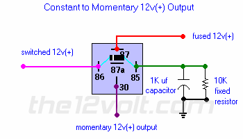
Replies:
Posted By: dualsport
Date Posted: March 14, 2007 at 1:03 AM
That's not a time delay setup, it's for getting a momentary output from a switched input that's steady on after turning on.
The relay will switch on instantly when the switched input is applied.
The capacitor provides the ground path, and as it charges up through the relay coil, it opens up the relay again in a short time, no matter how long the switched 12V input stays on.
The 10K resistor bleeds down the voltage across the cap after the switch signal is turned off, to prep it for the next cycle.
Posted By: whkoski
Date Posted: March 14, 2007 at 7:38 AM
I apologize for not explaining the change I've made to the circuilt. I'm not using pin 87 of the relay. Instead, the switched 12V output from pin 86 will also connect to pin 87a. When the coil is energized, pin 30 won't see the 12V switched output for aproximately 1/2 second. I'd like to have a 2 second delay, so I'm wondering what size capacitor I need.
Posted By: hotwaterwizard
Date Posted: March 14, 2007 at 8:03 AM
Sounds like a timer to me. A Delayed off timer to be exact. When power is applied to the Resistor Capacitor network , the fully charged capacitor begins to discharge thru the resistor and the coil of the relay causing the voltage to drop out at a time set by the resistance and capacitance. It does qualify as a simple timer. https://www.rwc.uc.edu/koehler/biophys/4g.html These calculators are for series circuits. The circuit here is not a series circuit it is a Parallel circuit. https://www.play-hookey.com/dc_theory/rlc_circuits.html https://www.cvs1.uklinux.net/cgi-bin/calculators/time_const.cgi https://ourworld.compuserve.com/homepages/Bill_Bowden/rc.htm ------------- John DeRosa (Hotwaterwizard)
Stockton California
When in doubt, try it out !
Posted By: hotwaterwizard
Date Posted: March 14, 2007 at 8:26 AM
Looks like 4 capacitors in parallel may do it. 1000 uf each. Not in series. Capacitors work different than speakers or resistors the add up in Parallel. Try adding a transistor for better time control. 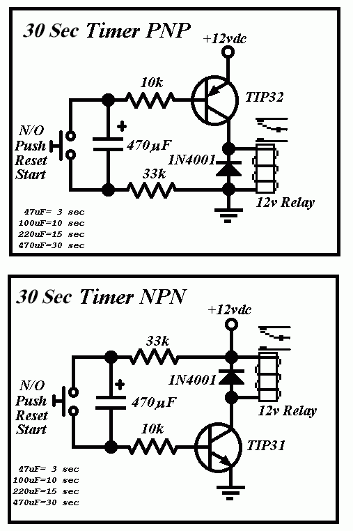
------------- John DeRosa (Hotwaterwizard)
Stockton California
When in doubt, try it out !
Posted By: dualsport
Date Posted: March 14, 2007 at 8:33 AM
Your timer delay is going to be dependent on the resistance of the relay coil you're using, so if you found it's giving you 1/2 sec now, and you want about 2 sec, then you just multiply the cap value by 4.
Using a transistor to switch the relay, and having a resistor-cap network to control the transistor would be much better than directly driving the relay coil in that way, so you don't need to use these big caps. 4000 uF 20V caps aren't all that tiny or cheap.
With the setup you're planning, it's going to momentarily spike up at the start before turning off again for the delay period-
Don't know if that might be a problem for what you're using this for. If it's a mechanical system you're driving, it'd probably be okay, but if you're using it as a trigger for an electronic circuit, it'll trigger it prematurely.
|