break up long pulse from relay
Printed From: the12volt.com
Forum Name: Relays
Forum Discription: Relay Diagrams, SPDT Relays, SPST Relays, DPDT Relays, Latching Relays, etc.
URL: https://www.the12volt.com/installbay/forum_posts.asp?tid=93836
Printed Date: December 30, 2025 at 2:01 PM
Topic: break up long pulse from relay
Posted By: petie-tl
Subject: break up long pulse from relay
Date Posted: May 12, 2007 at 2:14 AM
I added a relay to flash lights and honk horn when I lock the doors with my remote.... 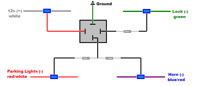 Everything works great but the pulse is about a half second long, which doesn't sound long but the horn is too loud even for just a half second. How can I break up the pulse so the horn either beeps twice or only beeps for half as long as it currently does? If this is done by adding a capacitor, what size/type capacitor should I use and where does it go? I have a 98 Acura TL 3.2 -- thanks!!
Replies:
Posted By: hotwaterwizard
Date Posted: May 14, 2007 at 8:44 AM
Most timers are one second or longer. You can stick a sock in the horn to muffle the sound. ------------- John DeRosa (Hotwaterwizard)
Stockton California
When in doubt, try it out !
Posted By: hotwaterwizard
Date Posted: May 14, 2007 at 8:46 AM
I can't believe I just told someone to stick a sock in it. LOL
-------------
John DeRosa (Hotwaterwizard)
Stockton California
When in doubt, try it out !
Posted By: dualsport
Date Posted: May 14, 2007 at 12:57 PM
If you don't have any socks to spare :), you can just use the constant to momentary relay circuit featured on the relay circuit pages to do the job. Since it's such a short pulse output you're looking for, it should work okay with the direct drive setup pictured there.
Posted By: hotwaterwizard
Date Posted: May 14, 2007 at 2:43 PM
You mean this one? https://www.the12volt.com/relays/page5.asp#ctm 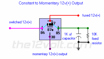
------------- John DeRosa (Hotwaterwizard)
Stockton California
When in doubt, try it out !
Posted By: hotwaterwizard
Date Posted: May 14, 2007 at 2:56 PM
Here is the new combined diagram You may have to use a smaller capacitor like 470uF 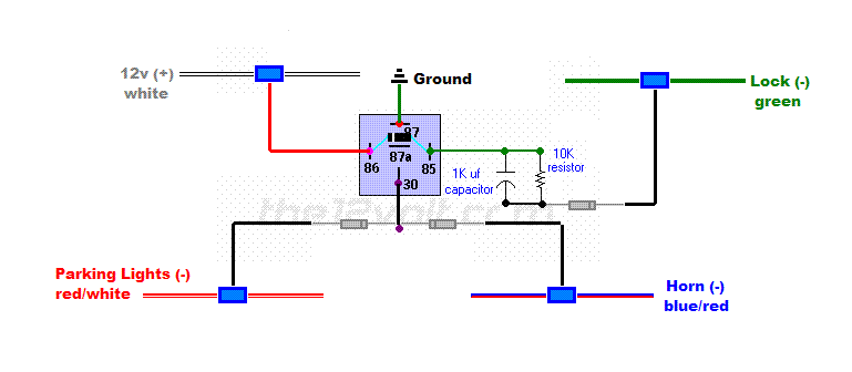
------------- John DeRosa (Hotwaterwizard)
Stockton California
When in doubt, try it out !
Posted By: dualsport
Date Posted: May 14, 2007 at 4:12 PM
Yeah, that looks good- Since the timing is affected by the relay being used, a heavy duty relay with a low coil resistance will give a shorter pulse time and the honk will be shorter.
Just diddle around with the cap values to get the toot you want; use the smaller cap for a shorter honk.
Posted By: dualsport
Date Posted: May 14, 2007 at 4:23 PM
Just a comment for anyone using the big cap setup; since it'll most likely have to be a polarized electrolytic to get that kind of capacitance, make sure the polarity is wired correctly, with the positive side to the 12V, as shown in the diagram.
They don't take reverse polarity connections too well, so don't just connect it up any ole way, double check the polarity before powering it up.
If you don't need to pulse it in rapid succession, you can use a larger value of resistance (the 10k resistor) to reduce the standby drain on the battery (12V / 10k = 1.2mA). All that will mean is that it'll take longer for it to discharge the cap and reset for a second pulse output.
Whether that's important is up to you.
Posted By: petie-tl
Date Posted: June 04, 2007 at 7:44 PM
Thanks for the help guys. I'm going to try this with a 470uF cap and a 10k resistor....
1. Do I need a diode connecting pins 85 and 86 as pictured? And if it's not too much trouble, I was wondering why a diode would be needed there?
2. I got a 470uF axial capacitor with arrows on it that point in one direction. Do I wire this in with the arrows pointed up?
Posted By: petie-tl
Date Posted: June 04, 2007 at 7:52 PM
petie-tl wrote:
Do I wire this in with the arrows pointed up?
Just to clarify, I meant "pointed up" as in the same direction that is shown in the above diagram.
Also, just wondering.... if I were to forget about the cap and resistor, and use a piezo buzzer (that has one red wire and one black) instead of the Horn(-) in the above diagram, would I need to add another relay? How would I wire up the piezo buzzer instead of the horn? ------------- petie
'98 Acura TL 3.2
Posted By: dualsport
Date Posted: June 04, 2007 at 9:02 PM
You could do without the diode if you want. It's just general good practice to add a supression diode to control voltage spikes that normally occur when a relay turns off, to avoid damaging sensitive electronic circuits being used to drive it. The cap acts as a buffer anyway.
The arrow on the cap should have a marker like a (-) on it, and should point towards the leg that's negative. The other side is the positive and you'd then want to connect it towards the 12V source, which would be to the relay.
The relay in the diagram just connects relay terminals 87 and 30 briefly when your lock input goes active, so you can hook up your buzzer with one end at 12V and the other end to the relay. If you want it to switch 12V rather than ground as shown, you would connect 12V to relay terminal 87 instead of ground.
Posted By: dualsport
Date Posted: June 04, 2007 at 9:09 PM
petie-tl wrote:
if I were to forget about the cap and resistor, and use a piezo buzzer (that has one red wire and one black) instead of the Horn(-) in the above diagram, would I need to add another relay? How would I wire up the piezo buzzer instead of the horn?
If you mean you want to forget about the momentary output business, and use a piezo buzzer instead of the horn to give you your audio feedback, then you could just connect 12V to the red of your buzzer, and the black directly to your lock (-) output control. I'm assuming your buzzer just needs 12V DC, and draws next to no power, so the lock output can drive it without any problem. Then you can just disconnect your horn and it wouldn't be as annoying.
Posted By: petie-tl
Date Posted: June 09, 2007 at 7:07 PM
I tried adding the piezo buzzer both of the ways pictured below but the buzzer does not sound.... which diagram is correct??
Diagram 1:
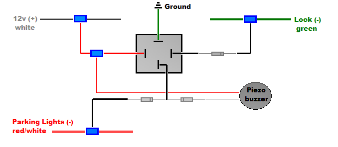
Diagram 2:
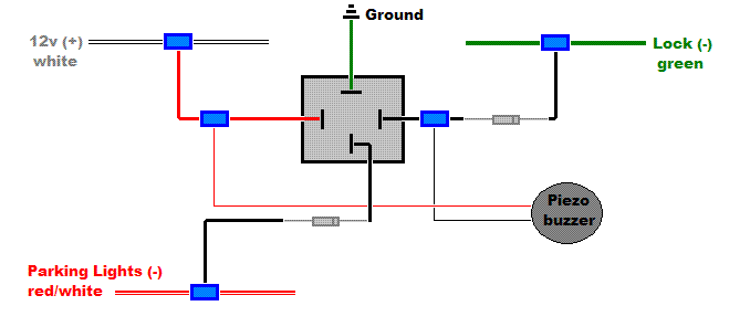
Here are the specs on the buzzer....
Pulsing Piezo Buzzer
1 red wire, 1 black wire
Voltage range: 3.0-28VDC
Current consumption: 12mA max at 12VDC
Sound pressure level: 90dB min at 30cm/12VDC
Resonant frequency: 2800 +/- 500Hz
Pulse rate: 3.5Hz +/- 20%
Could the buzzer be the problem? If so, what kind of buzzer should I be using?? ------------- petie
'98 Acura TL 3.2
Posted By: dualsport
Date Posted: June 09, 2007 at 11:22 PM
Either one should work-
Do you hear the buzzer when you just connect it up directly to 12V and ground? If your parking lights flash, it should buzz, unless your buzzer is busted or was connected backwards.
Posted By: dualsport
Date Posted: June 10, 2007 at 12:22 AM
You described your buzzer as a "Pulsing Piezo Buzzer";
It may be set up to output a beep-beep-beep sound, so it might take a bit of time before it starts sounding. Depends on how the internal oscillator circuitry is designed.
If you just touch the 12V power briefly to your buzzer briefly, does it start sounding off immediately as soon as you make contact? If not, then you'll want to get a continous sounding buzzer for this application.
Posted By: petie-tl
Date Posted: June 16, 2007 at 1:29 PM
Got a regular (not pulsing) piezo buzzer and it works!! Thanks!!!!
-------------
petie
'98 Acura TL 3.2
|


