turn signal, brake priority relay setup
Printed From: the12volt.com
Forum Name: Relays
Forum Discription: Relay Diagrams, SPDT Relays, SPST Relays, DPDT Relays, Latching Relays, etc.
URL: https://www.the12volt.com/installbay/forum_posts.asp?tid=94499
Printed Date: January 31, 2026 at 12:12 PM
Topic: turn signal, brake priority relay setup
Posted By: bwinkler
Subject: turn signal, brake priority relay setup
Date Posted: June 03, 2007 at 10:13 PM
If you view the link below, it will take you to the original topic in which I am unable to post a question since it has been closed. https://www.the12volt.com/installbay/forum_posts.asp?tid=83462&PN=1&tpn=1 I had the liberty to try the two relay setup using two Bosch 0 332 209 150 12V 20/30A relays, and two 1N4001 diodes. Since this was an experiment, only one side was put together to test the results. The experiment involves a bread board, 9V DC battery and associated alligator clips and small gauage wiring. I checked and double checked the wiring and I can not get this two relay setup to work correctly. When the brake and turn signals operate indepently of each other, the circuit works like it should. Only when both brake and turn signals energized the circuit seems askew. The test lamp is full bright when the brake is engaged, I then switch the turn signal input off and on and lamp does not fully turn off. The lamp dims instead of going off. All the parts are in good working order, I even tried spare relays and diodes to see if they were malfunctioning but they all react the same. This project is for my '03 Dodge Caravan that has the red and red brake/turn signals. I absolutely love the van, but find the rear lights a little shy of safety in the brake/turn signal combo in my opinion. I'm scratching my head on this....any help on this topic would be greatly appreciated. ____ Brian ------------- ________________
Brian D. Winkler
Replies:
Posted By: hotwaterwizard
Date Posted: June 07, 2007 at 11:30 PM
Let me see if I understand what you need. 2 filiments with 3 functions. 1) Low is regular tail lights with the lights on it is lit. 2) Brakes when break pedal pushed 3) blinker over rides break and only one side blinks while the other still steady. Hmm Sounds like trailer wiring.. ------------- John DeRosa (Hotwaterwizard)
Stockton California
When in doubt, try it out !
Posted By: hotwaterwizard
Date Posted: June 08, 2007 at 8:31 AM
Try this. One Relay Circuit for each side. 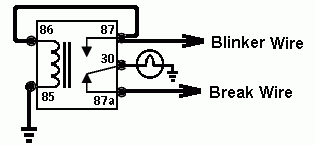
------------- John DeRosa (Hotwaterwizard)
Stockton California
When in doubt, try it out !
Posted By: bwinkler
Date Posted: June 08, 2007 at 5:08 PM
My initial thought was this setup may work, then after experimenting with it I found it does not. Especially not with the bosch relays I have on hand. There is no delay between the 87 & 87a switching so the brake is the override in this setup. I'm not sure if there is a relay that has built in delay for this feature. You may be right in saying this can be as simple as a trailing wiring hookup. The dodge caravan I have has independent brake and turn signal bulbs. I want the brake bulb to flash with the turn signal circuit. You may have seen this in the real world, the brake bulb and turn signals are red which makes it rather difficult to see when trailing these vehicles. Chrysler/Dodge got smart in '05 and changed it over to one bulb for both brake/turn signal operation. Thanks for your help thus far, I will continue to research this. hotwaterwizard wrote:
Try this. One Relay Circuit for each side. 
------------- ________________
Brian D. Winkler
Posted By: hotwaterwizard
Date Posted: June 08, 2007 at 10:30 PM
While Driving to work I realized that it will not work. I thought about it all day. I took a couple of hours to analize it. Here is what I came up with.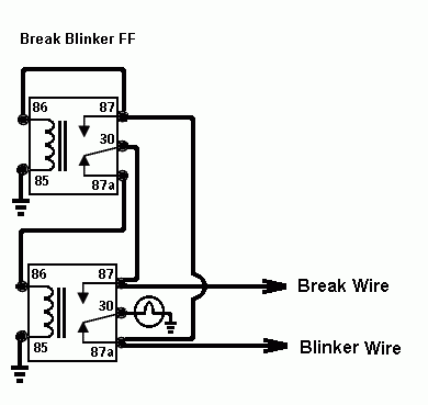 Blinker is hooked to the light thru the bottom relay. If the Blinker is off and the brake is hit the Relay latches to the Break circuit until you let off the break. If you turn on the blinker durring this cycle the top relay will unlatch the relay and allow the blinker to flash. ------------- John DeRosa (Hotwaterwizard)
Stockton California
When in doubt, try it out !
Posted By: hotwaterwizard
Date Posted: June 08, 2007 at 11:08 PM
Here is the same circuit with cube relays. 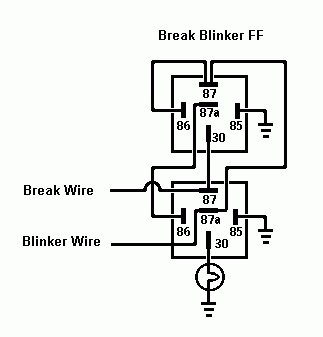
------------- John DeRosa (Hotwaterwizard)
Stockton California
When in doubt, try it out !
Posted By: bwinkler
Date Posted: June 09, 2007 at 12:19 AM
Thanks hotwater, I will play around with this tomorrow. hotwaterwizard wrote:
Here is the same circuit with cube relays. 
------------- ________________
Brian D. Winkler
Posted By: hotwaterwizard
Date Posted: June 09, 2007 at 12:37 AM
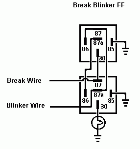 ------------- John DeRosa (Hotwaterwizard)
Stockton California
When in doubt, try it out !
Posted By: dualsport
Date Posted: June 09, 2007 at 8:47 AM
hotwaterwizard wrote:

It looks like it would leave the light would on whenever either the brake or turn signal is on; need to tweak the circuit so that the T/S input will interrupt the brake signal when it's on but leave the light off at that time, so it'll blink instead of staying steady on.
Also have to prevent the blinker signal from feeding back into the brake input, otherwise both sides will blink in hazard light fashion whenever the blinkers are on.
Posted By: dualsport
Date Posted: June 09, 2007 at 10:47 AM
Here's a modification that should isolate the two inputs and allow the one side to blink when the brakes are on- basically just turns off the lamp whenever both the brake and T/S are on at the same time, but passes it through normally when only one is on at a time. 
Posted By: hotwaterwizard
Date Posted: June 09, 2007 at 6:46 PM
Show me in my diagram where the two circuits are connected. I can not see where they connect to each other. They are already Isolated as far as I can see. The last one posted is a direct short between break and Blinker system. Keep it simple it makes less problems. 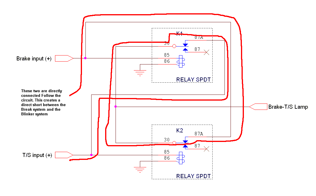
------------- John DeRosa (Hotwaterwizard)
Stockton California
When in doubt, try it out !
Posted By: hotwaterwizard
Date Posted: June 09, 2007 at 7:26 PM
I bench tested mine and it works perfectly as designed. It only latches if the Blinker signal does not flash. Every time it flashes it latches and unlatches as it is designed to do. 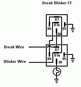
------------- John DeRosa (Hotwaterwizard)
Stockton California
When in doubt, try it out !
Posted By: dualsport
Date Posted: June 09, 2007 at 11:34 PM
hotwaterwizard wrote:

When you bench tested it, did you wire up both sides?
If the blinker is at 12V, you have 12V at terminal 87 of the top relay.
That's connected to the top relay's coil, so it gets energized.
When the relay is energized, 87 is connected to 30.
30 is connected to the bottom relay terminal 87, which is connected to your Break Wire input, which I'm assuming is connected to the other side also.
That ends up turning on the light on both sides, which makes it like a hazard light instead of a turn signal.
Posted By: bwinkler
Date Posted: June 09, 2007 at 11:41 PM
You're right about the direct short, this can be easily fixed though. The circuit shown below, +12V will break the continuity between the two sources in a normal case. I tested this circuit on my bread board and it worked like it should for one side. To keep it safe from stray voltages bleeding to the other side, a diode inline at each 30 pin output would clean the problem. hotwaterwizard wrote:
Show me in my diagram where the two circuits are connected. I can not see where they connect to each other. They are already Isolated as far as I can see. 
------------- ________________
Brian D. Winkler
Posted By: dualsport
Date Posted: June 09, 2007 at 11:44 PM
hotwaterwizard wrote:
Show me in my diagram where the two circuits are connected. I can not see where they connect to each other. They are already Isolated as far as I can see.
The last one posted is a direct short between break and Blinker system.
Keep it simple it makes less problems.

Don't forget the path connections involves relays.
It's shorted only when both inputs are off, so it doesn't matter, zero volta on both inputs.
When *either* one goes active high, the relay turns on, and the connection you outlined is no longer present- it's actually a pretty simple setup.
Think of it like a XOR (exclusive OR) circuit: when one is high and the other is low, the output is high. When both are high or both are low, the output is low. It should be exactly the behavior needed for this application.
Posted By: dualsport
Date Posted: June 10, 2007 at 12:11 AM
bwinkler wrote:
To keep it safe from stray voltages bleeding to the other side, a diode inline at each 30 pin output would clean the problem.
It's simply not a problem amd unnecessary, but if you're really worried about two zero volt signals being connected together and really want to use a diode, you'll need to use a high current capable diode.
Keep in mind the path isn't simply relay coil current but power to the bulbs, which will need relatively high current.
All it would do is add another possible point of failure and waste power by dropping voltage unnecessarily. Don't do it- keep it simple.
Posted By: hotwaterwizard
Date Posted: June 10, 2007 at 1:19 PM
The blinkers are seperate and only one side will blink when it's corrosponding blinker is activated. The blinkers are isolated from one another. how can they trigger both sides when isolated. ------------- John DeRosa (Hotwaterwizard)
Stockton California
When in doubt, try it out !
Posted By: dualsport
Date Posted: June 10, 2007 at 9:54 PM
Well, there should be a single brake line wire going to both the left and right sides, unless the brake switch is a double pole type.
When the blinker signal sends power backwards to the brake wire as I described earlier, it would turn on the other side at the same time. You can wiring up the second side in your bench test to confirm this, I haven't tried it; I'm only basing it on the diagram.
Posted By: hotwaterwizard
Date Posted: June 11, 2007 at 9:27 PM
After taking a second look at it I see what you are talking about. It works but I think a couple of Diodes would resolve the problem. The Diodes need to be heavy duty enough to handle the Bulb current . However it will not fix the crow that I am eating now. 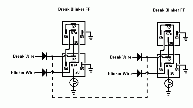
------------- John DeRosa (Hotwaterwizard)
Stockton California
When in doubt, try it out !
Posted By: dualsport
Date Posted: June 12, 2007 at 9:47 PM
That looks good; all it needed was a bit of a tweak, and just adding a couple diodes at the brake wire inputs would do the job. Probably don't need the ones at the Blinker Wire inputs, so you can do it with just the two. Replacing the dotted line connection with the diodes is all it needed.
Lots of ways to skin a cat; that's what makes things interesting. Beats doing crossword puzzles.. 
Posted By: hotwaterwizard
Date Posted: June 13, 2007 at 7:34 AM
The dotted line is suppose to represent the internal break wiring in the car.
-------------
John DeRosa (Hotwaterwizard)
Stockton California
When in doubt, try it out !
Posted By: dualsport
Date Posted: June 13, 2007 at 8:14 AM
If that's the connection between the two sides, then it should be on the other side of the diodes or else one side would still feed the other when the T/S is on-
Posted By: hotwaterwizard
Date Posted: June 13, 2007 at 8:33 AM
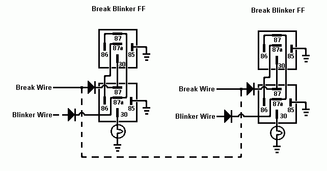 ------------- John DeRosa (Hotwaterwizard)
Stockton California
When in doubt, try it out !
Posted By: bwinkler
Date Posted: June 16, 2007 at 11:38 PM
Gentlemen, Hotwaterwizard: I was not able to get the circuit you described to work the first time without the diodes. I was just on vacation so I've been out of touch for the last week. I will try using the diodes just to play. Dualsport: The XOR type circuit works great. You're right, it really doesn't need diodes. When voltage is present, the relay will react to keep discontinuity. I find this trial a sucess. It is great this info can be available for folks to build for themselves, get to know (maybe) electricity a little better and appreciate what its worth. This simple circuit can be bought in a camper/trailer type store, but the deal was like $30+ dollars. Through the use partsexpress.com, I was able to get all the necessary pieces for less and build it myself. I also get to know my car a little better, too. ------------- ________________
Brian D. Winkler
Posted By: bwinkler
Date Posted: June 24, 2007 at 10:25 PM
dualsport wrote:
Here's a modification that should isolate the two inputs and allow the one side to blink when the brakes are on- basically just turns off the lamp whenever both the brake and T/S are on at the same time, but passes it through normally when only one is on at a time.
I have decided to use the circuit described by Dual Sport. I was able to put the circuit together and try it out on the van. The circuit works just like it is supposed to. However, I found out that when brake and turn signal are on simulataneously, the flash rate of Blinker is too fast. This makes sense because the T/S (Turn Signal) input only operates the coil of the relay for brake input. During this condition and only this condition, the T/S flasher up front reads this as load missing at the rear, the relay coil impedance must be very small. To defeat this, I figure putting a resistor in the circuit matching the rating of the bulb. The bulb is rated 27 Watts, at full voltage (14V). The resistor to match the 27 watt rating would have to be fairly large according to some website data. I put some thought into, the T/S is not on continuously but in a flash condition. My question is, could I get away with a lower wattage resistor (say 10W?) knowing the load will not be continuous? Without getting into too in dept with the flash rate, amount of time the resistor will sees load off and on yield a value suitably less than the bulb specification. Any thoughts? ------------- ________________
Brian D. Winkler
Posted By: dualsport
Date Posted: June 24, 2007 at 11:25 PM
You might try getting an electronic flasher if you're currently using a standard version. They're designed with electronic circuits to make and break the circuit, and less sensitive to the load. They're commonly used when lamps are replaced with LEDs, which draw very little current compared to the original lamps. EP-26
You really want to avoid adding load resistors because they'll get pretty hot. Hot glue guns and soldering irons are about 20W, and you can see how hot they get. If you really have to do it that way, you might just wire in a bulb with sufficient wattage instead of resistors, by dissipating some of that energy as light rather than pure heat, it'd be cooler.
Posted By: bwinkler
Date Posted: June 26, 2007 at 6:48 AM
dualsport wrote:
You might try getting an electronic flasher if you're currently using a standard version. They're designed with electronic circuits to make and break the circuit, and less sensitive to the load. They're commonly used when lamps are replaced with LEDs, which draw very little current compared to the original lamps. EP-26 .
The only problem with that method is that this vehicle has onboard control modules. I was not able to find a flasher box anywhere. Then I reviewed the repair manual it does not list a flasher relay but an integrated control module, ICM or sometimes called the BCM. The way this van was designed rules out option 1.
dualsport wrote:
You really want to avoid adding load resistors because they'll get pretty hot. Hot glue guns and soldering irons are about 20W, and you can see how hot they get. If you really have to do it that way, you might just wire in a bulb with sufficient wattage instead of resistors, by dissipating some of that energy as light rather than pure heat, it'd be cooler.
Do you really think it will get that hot with the on and off operation? If the resistor were to be powered on continously, then yes with no doubt fear of the heat issue. It has been on my mind, too, just to wire the same lamp in place of the resistor. The same lamp held in my hand with cloth on the glass does not get hot while flashing.... ------------- ________________
Brian D. Winkler
Posted By: hotwaterwizard
Date Posted: June 26, 2007 at 7:42 AM
Spent hours figuring mine out. No thank you just negitive remarks. ------------- John DeRosa (Hotwaterwizard)
Stockton California
When in doubt, try it out !
Posted By: bwinkler
Date Posted: June 26, 2007 at 8:45 AM
hotwaterwizard wrote:
Spent hours figuring mine out. No thank you just negitive remarks.
hotwaterwizard: I do not know of any negative remarks by me. And I mean to the nature of hurting your feelings. I was not able to get the circuit you illustrated to work on my bread board and stated my findings. In no way shape or form am I questioning your ability to create and invent circuits for different applications. I thank you for your efforts, I spent several hours testing this stuff as well. Sorry for the delay. ------------- ________________
Brian D. Winkler
Posted By: hotwaterwizard
Date Posted: June 26, 2007 at 8:48 AM
I figured out that I shouldn't post anything before I drink my morning Coffee. Sorry not quite awake yet. ------------- John DeRosa (Hotwaterwizard)
Stockton California
When in doubt, try it out !
Posted By: dualsport
Date Posted: June 26, 2007 at 9:17 AM
Hotwaterwizard can be counted on to come up with a nicely drawn out circuit no matter what the problem, so definitely a help on the forum for everyone. If just one of those circuits need a tweak to optimize it, out of hundreds, it's still a great batting percentage.
If your vehicle uses an integrated lighting control module, then you probably should go with the added load to deal with the lamp outage function.
If you need to add the load to the circuit, connect it across the K1 top relay from 87A to ground. That way you won't get doubled load when the brakes are applied, but it instead shunts the load to your resistor or light bulb.
The advantage of the light bulb is less heat at the cost of reliability, since it could break or burn out. I'd still go with a bulb; just wire in a socket from 87A to ground. If it burns out you'll know it.
Posted By: dragracerjosh
Date Posted: August 16, 2007 at 12:09 PM
I cant get the picture to load of Dualsports diagram. I am having the same problem and a heck of a time trying to figure it out.... I have been using DPDT relays with no diodes and I can only get independant turn signals but when the brakes light up it overrides... I would like to start from scratch with a better setup.... PLEASE HELP>>> Thanks, Josh
Posted By: dualsport
Date Posted: August 17, 2007 at 12:36 AM
Does this Link work for you?
Posted By: dragracerjosh
Date Posted: August 17, 2007 at 6:40 AM
no it just gets to half on the status bar and says the page cannot be displayed. I have tryed it on 3 different computers... My email is dragracerjosh2001@yahoo.com if there is any way you could send it there??? I really appreciate this I have been fighting with my lights and relays for over 2 weeks steady.... thanks, Josh
Posted By: dualsport
Date Posted: August 17, 2007 at 7:37 AM
Strange- are your computers able to display .png files? Emailed the file over, see if that works.
Posted By: hotwaterwizard
Date Posted: August 17, 2007 at 8:34 AM
Here is the picture from Dualsport in a different format.  ------------- John DeRosa (Hotwaterwizard)
Stockton California
When in doubt, try it out !
Posted By: dragracerjosh
Date Posted: August 17, 2007 at 9:42 AM
John, the thing scaring me from using yours is the diodes. I have no clue what ones to use. I have a Radio shack right around the corner... Any recomendations on a diode?? DualSport, my computers must not work with .png files. I appreciate your trying but I am having no luck at all opening the file... Thank You Both, Josh
Posted By: dualsport
Date Posted: August 17, 2007 at 1:49 PM
Well, weird how you can't view .png files, they're supposed to be Portable. How about a jpg then? https://img178.imageshack.us/img178/3387/priorltsac6.jpg
Posted By: hotwaterwizard
Date Posted: August 17, 2007 at 10:46 PM
1N4001 Micro 1A Diodes Model: 1N4001 $0.59 Radioshack Catalog #: 276-1101
 Click on the picture to go to the page Here is the file from Dualsport 
------------- John DeRosa (Hotwaterwizard)
Stockton California
When in doubt, try it out !
Posted By: dragracerjosh
Date Posted: August 18, 2007 at 1:58 PM
I cannot thank you guys enough!!! My work computer wouldnt open them even in jpeg, but when I got home last nite I could see them and after some tinkering the circuit works PERFECT!!! My lowrider is ready for the road now.... Thank you both VERY MUCH!!!!!! Josh
Posted By: dualsport
Date Posted: August 18, 2007 at 4:04 PM
Glad it finally worked! 
Posted By: hotwaterwizard
Date Posted: August 20, 2007 at 8:18 AM
Which one did you end up using?
-------------
John DeRosa (Hotwaterwizard)
Stockton California
When in doubt, try it out !
|


