actuated lisence plate
Printed From: the12volt.com
Forum Name: Relays
Forum Discription: Relay Diagrams, SPDT Relays, SPST Relays, DPDT Relays, Latching Relays, etc.
URL: https://www.the12volt.com/installbay/forum_posts.asp?tid=94958
Printed Date: January 31, 2026 at 5:54 AM
Topic: actuated lisence plate
Posted By: hallperson
Subject: actuated lisence plate
Date Posted: June 20, 2007 at 5:09 PM
i have a actuated lisence plate that currently move by a toggle switch up and down i am tryin to get it to come down when the truck is on and go up when the truck is off any help with diagrams would help me alot
Replies:
Posted By: hotwaterwizard
Date Posted: June 20, 2007 at 8:04 PM
Show me how your switch is wired right now.
-------------
John DeRosa (Hotwaterwizard)
Stockton California
When in doubt, try it out !
Posted By: hallperson
Date Posted: June 20, 2007 at 8:55 PM
its is just a toggle switch that reverses polarity so it can go up and down there are only two wires that run back to the actuator
Posted By: hallperson
Date Posted: June 20, 2007 at 9:30 PM
i found similar threads about this but most involved some kind of switch. i want it to run all on its own, so if i get in my truck and turn it on the plate will drop and when i stop and turn the truck off the plate goes up. its pretty much the same way a power antenna works you turn the radio on and it goes up you turn it off it goes down.
thanks alot joe
Posted By: dualsport
Date Posted: June 21, 2007 at 7:20 AM
Is your current setup timed to turn off the power automatically or are you doing it manually? .
Posted By: hotwaterwizard
Date Posted: June 21, 2007 at 8:32 AM

This is asuming the plate has automatic limit switches like an Electric Antenna does. This just switches polarity when the key switch is on. ------------- John DeRosa (Hotwaterwizard)
Stockton California
When in doubt, try it out !
Posted By: hallperson
Date Posted: June 21, 2007 at 4:04 PM
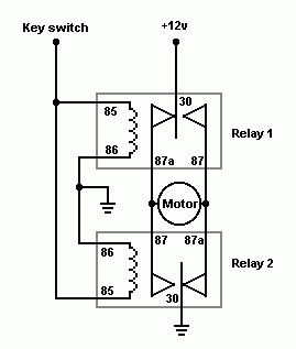
the relays shown in your diagram are they std. 30/40amp relays, it is a little bit confusing to what goes where
Posted By: hallperson
Date Posted: June 21, 2007 at 4:05 PM
the actuator does have limit switches so it will stop itself when its all the way up and all the way down
Posted By: dualsport
Date Posted: June 21, 2007 at 8:11 PM
hotwaterwizard wrote:

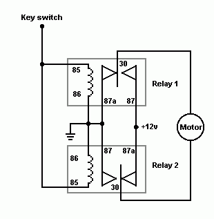
Hotwaterwizard, could you switch the relays around so that the common of the relays are connected to the "motor" inputs, with the 12V and ground on the 87 and 87A?
That would avoid any chance of one of the relays lagging the other when switching, and momentarily connecting the 12V directly to ground. If the common side is on the motor inputs, it wouldn't matter if the relays aren't perfectly synchronized.
Posted By: hotwaterwizard
Date Posted: June 21, 2007 at 11:23 PM
I don't see why it is confusing all the numbers are marked on each relay and wire. What more do you need. They are marked clearly. For you Dualsport. 
------------- John DeRosa (Hotwaterwizard)
Stockton California
When in doubt, try it out !
Posted By: dualsport
Date Posted: June 21, 2007 at 11:35 PM
Posted By: hotwaterwizard
Date Posted: June 21, 2007 at 11:36 PM
Okay lets spell it out. 85 and 85 from both relays go to the key switch. 86 and 86 of both relays go to ground 87a of relay 1 and 87 of relay 2 go to ground too. 87 of relay 1 and 87a of relay 2 go to +12v The actuator wires go on 30 of relay 1 and 30 of relay 2. If it does the opposite of what you want just switch the actuator wires around, ------------- John DeRosa (Hotwaterwizard)
Stockton California
When in doubt, try it out !
|


