push button switch to latching
Printed From: the12volt.com
Forum Name: Relays
Forum Discription: Relay Diagrams, SPDT Relays, SPST Relays, DPDT Relays, Latching Relays, etc.
URL: https://www.the12volt.com/installbay/forum_posts.asp?tid=96030
Printed Date: May 06, 2026 at 7:08 PM
Topic: push button switch to latching
Posted By: whitemage25
Subject: push button switch to latching
Date Posted: July 29, 2007 at 6:39 PM
I have a Bulgin push button switch that is NO and momentary, it is also has an illuminated ring. I want to use several of these in an install to activate 4 sets of PIAA off road lights(front, left, right, rear). Its not just a matter of the latching effect but I can't figure how to activate the LED ring in conjunction with the lights. Can anyone help with this? Thanks, Justin
Replies:
Posted By: whitemage25
Date Posted: August 04, 2007 at 1:49 AM
So I was trying to find an answer to this question but it seems like the only one on the site is the one that uses 4 or 5 relays(to many for my space constraints) or the one using the latching relay(have trouble figureing if this one would work or not.) Now I was looking at the wiring for the PIAA 525 Driving lights which have a low and high beam. they are controled by a small switch module that is just two momentary switches one for on and off and one for high and low modes. But the wiring only includes two relays....Anyone know how they pull this off? Or how I might duplicate it with my own push button switches? Or am I just missing something obvious? Thanks, Justin
Posted By: KPierson
Date Posted: August 04, 2007 at 10:21 AM
The control box most likely contains a processor that turns the momentary pulses in to latching on/off pulses. The processor would then drive a transistors that would run the two relays - one relay for high, one relay for low. It would be a pretty straight forward set up. Where did you purchase the push buttons from? I've been looking for some nice illuminated momentary push buttons. ------------- Kevin Pierson
Posted By: whitemage25
Date Posted: August 04, 2007 at 10:38 AM
I opened up the switch module and all I see on the PCB is the two switches and the two LED's, no sign of any processor's. Could you explane more about this straight forward set up? I really would like to use these switches and I'm having a really hard time tracking down their latching cousin's. Can anyone provide a link to a good latching relay for this set-up? Here is the switch website https://www.frozencpu.com/ele-70.html
Posted By: hotwaterwizard
Date Posted: August 06, 2007 at 1:23 AM
This is the picture of the switch provided by your link. It is wrong . 
Here is the correct Diagram 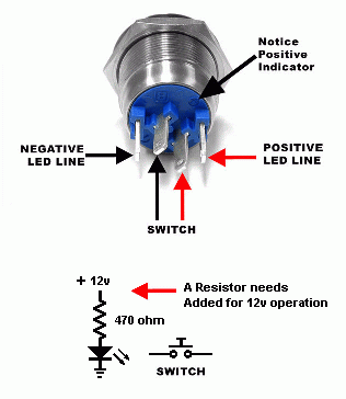
As for the relays here is how it is done. 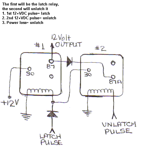
------------- John DeRosa (Hotwaterwizard)
Stockton California
When in doubt, try it out !
Posted By: hotwaterwizard
Date Posted: August 06, 2007 at 1:37 AM
Put it together and you get this. 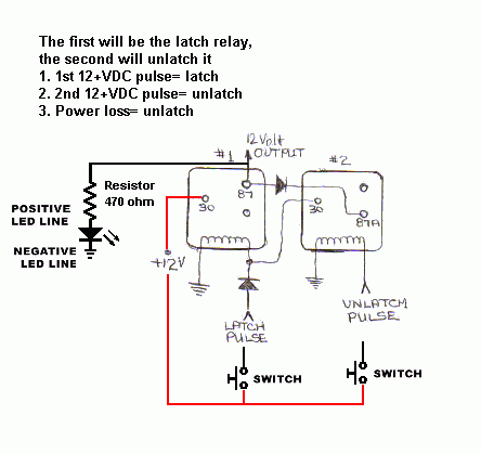
------------- John DeRosa (Hotwaterwizard)
Stockton California
When in doubt, try it out !
Posted By: hotwaterwizard
Date Posted: August 06, 2007 at 1:42 AM
Posted By: whitemage25
Date Posted: August 06, 2007 at 9:52 AM
Thanks for the info, very through, ...so the only way to do this is with two switches for each light? Guess I won't be using that switch after all... Also how is that diagram any different that yours other than the added LED info?
Posted By: KPierson
Date Posted: August 06, 2007 at 12:52 PM
The only way to use push button switches and bosch style relays is the way above. If you want to get more invovled you can do it with latching relays, flip flops, microcontrollers, etc. ------------- Kevin Pierson
Posted By: whitemage25
Date Posted: August 06, 2007 at 1:45 PM
How much more involved would it be to use latching relays? What kind of latching relay would I need? Can I modify the Single Pulse to Lock and Unlock on https://www.the12volt.com/relays/page5.asp to do what im looking for? If so where can I find that relay? I really want to use these switches its for a very unique panel on an install that I'm working for...I found the newer latching version of the switches but they are 18mm insted of 22mm and the button is hard to push. I'm thinking I might try and modify one of the Pilot tactile switch boxes to work with 4 of my switches but im still trying to figure that one out..... Thanks for all the info everyone......
Posted By: whitemage25
Date Posted: August 06, 2007 at 1:47 PM
The Pilot PL-SW16 is what im thinking of trying to modify...the tactile switches are just momentarys... Here is a site https://www.cardomain.com/item/PILPLSW16
Posted By: hotwaterwizard
Date Posted: August 06, 2007 at 3:10 PM
In this picture there is a Positive and Negitive voltage on the switch wires. This would cause a dead short across the power leads when the switch is pushed. Not good.
In this Picture you have the resistor added and the switch is just a switch. the positive and necitive wires are only shown on the LED.
With a toggle latching relay you would still need 2 switches. ------------- John DeRosa (Hotwaterwizard)
Stockton California
When in doubt, try it out !
Posted By: KPierson
Date Posted: August 06, 2007 at 3:14 PM
You could probably use the pilot box with no issues. It appears to have a 5 pin ribbon cable for 4 buttons, indicating that there is most likely one ground wire and 4 inputs. You should be able to rewire that cable to go through your 4 independent switches. You would then need to drive 4 relays with the pilot box, as it doesn't have high current outputs. For $20 that is the route I would go. ------------- Kevin Pierson
Posted By: whitemage25
Date Posted: August 06, 2007 at 11:27 PM
Yea I opened up the pilot box today...looks like it should do the trick, it's built pretty well which is odd seeing as how its a pilot and only cost 20 bucks. I'm gonna play with it tomorrow and make sure it will work, then I will start wiring everything into a new project box with harnesses insted of loose wire. I'll post some pics once i get started. Thanks again for all the help guys.
|