What is the draw on a realy coil?
How many relays can I run on a 200ma circuit?
I'm looking to run at least 2 on 200ma.
-------------
KingVinnie
Depends on the relay you're using; typical relay might draw about 160mA, but there are some high sensitivity relays that have higher impedance coils that draw less.
In general the heavier current handling relays need more power to close the contacts, so if you pick a relay that doesn't need much current to operate, it may not be able to handle the current you need to switch.
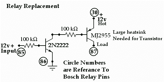
If use a transistor to drive your relay, you can pretty much drive an unlimited number of relays, controlled by your signal.
A BS170 MOSFET is controlled by voltage, rather than current, so you could use that to drive your relay, without affecting your control signal at all.

This is a way you can take advantage of the difference in the power needed to switch a relay on vs. the amount of power needed to hold it on after it's already switched on.
It takes significantly less power to keep a relay on than it takes to switch it on from an open position.
Adding a cap and resistor in series with the input allows the amount of power (and current) drawn by the relay to be decreased to a minimum, but still allow full power to be applied at the initial turn on period.
The cap is normally sitting at 0V when the relay is off, and at the instant the control signal is applied, full voltage is applied to the relay coil. As the cap starts to charge up, the current shifts to the resistor connected in parallel, which will be enough to keep the relay closed. Eventually the cap will charge fully, and no current flows through the cap, and the resistor limits the current through the coil to the minimum level needed (Determined by the drop out voltage spec for the relay being used)
This is more for minimizing the amount of power a relay uses though; if your output is unable to deliver enough current to drive all the relays you have connected, you'd still need to add a transistor driver to boost the available current.
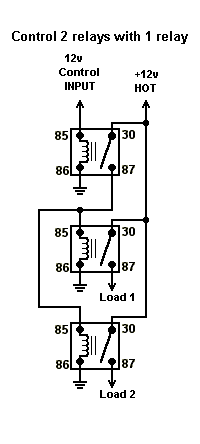
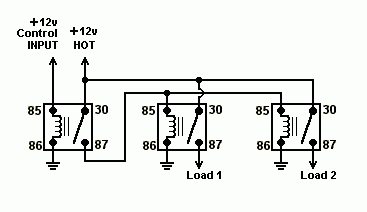
If you are using standard Bosch style relays you will not be able to get away with driving two relays with a 200mA signal.
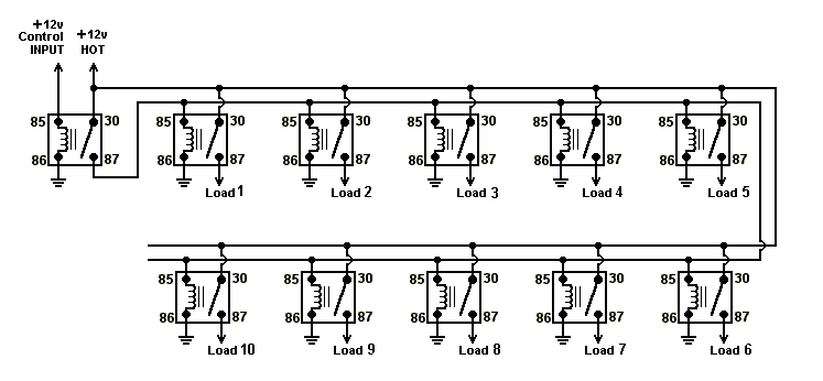
You would be best off to either use one relay to drive the other two, or use the first relays output to drive the 2nd relays coil (if the output is 12vdc).
-------------
Kevin Pierson
Great Idea Kevin!
I think that would be a great solution avoiding overload and prevent Frying the control power supply or transistor.
A couple of transistors could do also do the job.

-------------
John DeRosa (Hotwaterwizard)
Stockton California
When in doubt, try it out !

-------------
John DeRosa (Hotwaterwizard)
Stockton California
When in doubt, try it out !

-------------
John DeRosa (Hotwaterwizard)
Stockton California
When in doubt, try it out !
There are many options with this way of controlling multiple Relays

-------------
John DeRosa (Hotwaterwizard)
Stockton California
When in doubt, try it out !


