low water alarm
Printed From: the12volt.com
Forum Name: Vehicle Wiring Information & File Requests
Forum Discription: Request Car Alarm, Car Stereo, Cruise Control, Remote Starter, Navigation, Mobile Video, and Other Vehicle Specific Wiring Info, Manuals, Tech Tips
URL: https://www.the12volt.com/installbay/forum_posts.asp?tid=124321
Printed Date: March 27, 2026 at 9:31 AM
Topic: low water alarm
Posted By: maxedmini
Subject: low water alarm
Date Posted: November 07, 2010 at 1:01 PM
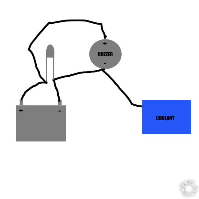
Hi there here is a circuit that i have so when water makes a earth the led and buzzer are activated this works fine BUT i would like it to work in reverse ie when the water drops below a set point the led and buzzer will activate.
i have tried using a spdt relay BUT the earth that is created through the water is not great enough to energize the coil in the relay.
is there another way this can be done
thanks
Replies:
Posted By: i am an idiot
Date Posted: November 07, 2010 at 3:27 PM
The way your diagram is drawn, the LED and the Buzzer will be on all the time. There is usually a float inside the reservoir that when low will connect the 2 contacts of a switch. The water is not used as a conductor.
Posted By: maxedmini
Date Posted: November 07, 2010 at 4:21 PM
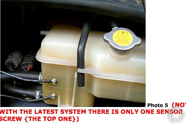
hi thanks for your reply i am creating a low level alarm as my car does not have one fitted and there is a system you can purchase that uses the water as a conductor to earth by simply inserting a self tapping screw into you header tank here is a picture from the install instruction showing the screws the latest kit only uses one screw to obtain a ground
Posted By: oldspark
Date Posted: November 07, 2010 at 7:32 PM
For that tank you would use a float system (eg, brake fluid level).
If using conductivity, use an AC system to avoid electrolysis. (I hope that self-tapper version uses AC.)
In your original post, a FET could be used. But it would be so unreliable - any contamination would appear as if fluid was still there.
Vehicles since the late 1980's have what they call "coolant sensors" which I though were "coolant level sensors" but may simply be temperature sensors (usually switches) for alarms etc as distinct from the temp gauge sensors. I have yet to investigate further.
Posted By: howie ll
Date Posted: November 08, 2010 at 2:17 PM
That photo....2 self taps into the header tank? I don't think so, especially if you live in a climate similar to where either Oldspark or Mr. Idiot live.
Come to think of it just try and drive into Central London on a nice summer's day.
Self tappers into plastic?
-------------
Amateurs assume, don't test and have problems; pros test first. I am not a free install service.
Read the installation manual, do a search here or online for your vehicle wiring before posting.
Posted By: oldspark
Date Posted: November 08, 2010 at 6:44 PM
The system pressure should be the same no matter where.
Mind you, my 45 year old vehicle has a 7psi system...
And that might be an unpressurised overflow tank which I think is more common these days (not to be confused with remote headers).
But you'd think only one probe (self tapper) would be needed - unless they are using a dc-offset ac.
But I bet it's a plain old dc system from someone that is none the wiser....
LOL - they used to make chips for fluid detection....
|