Hi there this is a simply circuit to detect low coolant BUT i need to add a delay to reduce false trigger when braking etc when the coolant is moving around
is this possible??
Any help would be great Thanks
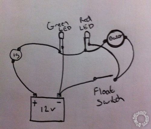
The Green LED will light with ignition and the red LED and buzzer will activate when the float switch is closed the LEDs and buzzer are 12v
Maybe something like:

from
bit-tech.net-RC delay and fan controller circuit.
Substitute your buzzer & red LED for the relay (upper RHS) with the two "
+12V" connected together, and the ground goes through your switch.
The FET (IRFZ46N) isn't critical - as long it is N-channel and handles the current you require (maybe 50mA or less for LED & buzzer - but even 20A-120A MOSFETs often only coast $2-$3).
Ideally the MOSFET will have internal protection diode... eg:

.
The operation is described fairly well in the
last post of the above link.
The on delay is proportional to the top resistor (ie, 150k; call it R1) times the capacitance C.
The discharge time of the capacitor is proportional to the lower resistor (ie, 100k; call it R2) time the capacitance C.
Hence delay is approx or proportional to:
R1 x C =
150k x 220 uF =
0.15 x 220 (M-Ohms & micro-F) =
33 seconds
(But Dreamslacker in the final post reckons it should be around 1 second.)
And the capacitor discharges thru R2 which is 100k. Compared to R1 (150k) its 2/3rds the resistance hence it will decay 3/2 = 50% faster than it charges thru R1 (since the RC time constant is t = RC)
I say approximate & proportional because t = RC is the time to charge or discharge to about 2/3rds of the voltage (1/e =~63%) - in this case 4.8V - whereas the FET turns on at about 4V (which is 4/4.8 = 83% charged; closer to 2xt).
And don't worry too much about the voltage of the Gate (compared to its Source S) - they usually tolerate up to 20V.
And the Gate current is negligible - ie, uA or less (compared to transistors that may be mA).
So as long as Vgs is above (say) 4V to 6V, the FET should be fully on.
But see wiki (esp. mosfet, maybe power-mosfet) or the link for theory. (Also RC time constant, voltage divider etc.)
Though sounding complex, I am merely trying to convey how non-critical the circuit values are. (Whereas transistors need specific base (- gate) currents & voltages etc....)