remote starter to multiple ignition wires
Printed From: the12volt.com
Forum Name: Vehicle Wiring Information & File Requests
Forum Discription: Request Car Alarm, Car Stereo, Cruise Control, Remote Starter, Navigation, Mobile Video, and Other Vehicle Specific Wiring Info, Manuals, Tech Tips
URL: https://www.the12volt.com/installbay/forum_posts.asp?tid=130811
Printed Date: April 30, 2026 at 5:59 PM
Topic: remote starter to multiple ignition wires
Posted By: mstec
Subject: remote starter to multiple ignition wires
Date Posted: March 04, 2012 at 8:23 PM
Hi there,
I am trying to get the Bulldog Deluxe 500 Remote Starter to work on my 97 BMW 540i. The problem is that my car has 3 (green) ignition wires. When I hook it up to only one of those ignition wires the car is cranking like crazy but wont run (start) the engine. I heard I have to use multiple relays to get it to work, but have no clue how. Can you guys please help me out?
Thanks,
Replies:
Posted By: kreg357
Date Posted: March 04, 2012 at 8:52 PM
Use the H1/5 Ignition2 output to control 2 external 30/40A SPDT relays.
Wire as follows :
Relay1
Pin 85 to Chassis Ground
Pin 86 to H1/5 Pink
Pin 87 to +12V constant thru 20A fuse
Pin 30 to 540 Ign2 Green
Pin87A not used
Relay2
Pin 85 to Chassis Ground
Pin 86 to H1/5 Pink
Pin 87 to +12V constant thru 20A fuse
Pin 30 to 540 Ign3 Green
Pin87A not used
Here is an install guide for another brand R/S with the diagram on Page 10 : https://www.readyremote.com/pdf/manuals/24921.pdf ------------- Soldering is fun!
Posted By: mstec
Date Posted: March 04, 2012 at 9:36 PM
kreg357 wrote:
Use the H1/5 Ignition2 output to control 2 external 30/40A SPDT relays.
Wire as follows :
Relay1
Pin 85 to Chassis Ground
Pin 86 to H1/5 Pink
Pin 87 to +12V constant thru 20A fuse
Pin 30 to 540 Ign2 Green
Pin87A not used
Relay2
Pin 85 to Chassis Ground
Pin 86 to H1/5 Pink
Pin 87 to +12V constant thru 20A fuse
Pin 30 to 540 Ign3 Green
Pin87A not used
Here is an install guide for another brand R/S with the diagram on Page 10 : https://www.readyremote.com/pdf/manuals/24921.pdf
kreg357, thank you so much for your help!
I have (according the vehicle wiring diagram) H1/5 (Pink) already hooked up to the cars Ignition#2 (Purple) wire. Which receives also +12v when ignition key is on position "ON" or "RUN" and "START" or "CRANK" position. So, in this case I have 4 ignition wires (3 green and 1 purple).
This a the wiring diagram for my car:
https://readyremote.com/main.asp?action=select&yr=3262&product=Remote%20Start&make=BMW&model=5%20Series
Posted By: oldspark
Date Posted: March 05, 2012 at 3:32 AM
I was thinking diodes instead, but I'd assume high currents are involved, else they'd have voltage drop issues.
But reliability wise, I'd stick with relays.
That's where typical ECU relays are good - eg, the JIDECO brown relay; one coil with 2 SPST contacts. Only one relay is then needed. (Though often harness-wired as a common input (+12V), these relays have 2 separate inputs - ie, a true dual SPST.)
These are common in Japanese vehicles, but maybe not elsewhere? (I don't know of a Bosch/Hella equivalent, though I rarely deal with them...)
Posted By: kreg357
Date Posted: March 05, 2012 at 6:40 AM
To power 4 ignition circuits and keep them all isolated, just add another relay to the diagram above. The Bulldog Deluxe 500's Ignition 2 output will not be connected directly to the 540. It will control the 3 relays and the relays will connect to the vehicles ignition circuits.
Relay3
Pin 85 to Chassis Ground
Pin 86 to H1/5 Pink
Pin 87 to +12V constant thru 20A fuse
Pin 30 to 540 Ign4 Purple
Pin87A not used ------------- Soldering is fun!
Posted By: howie ll
Date Posted: March 05, 2012 at 11:33 AM
Yes the vehicle's VIOLET (PURPLE) must be connected as an ignition wire.
No Peter relays not diodes, too much current.
This is the only vehicle I can think of like this, no other BMW and I've absolutely no idea why.
Brain fart by the designers?
-------------
Amateurs assume, don't test and have problems; pros test first. I am not a free install service.
Read the installation manual, do a search here or online for your vehicle wiring before posting.
Posted By: mstec
Date Posted: March 05, 2012 at 12:18 PM
Bulldog Tech Support just called me back saying:
- Use Ignition#1 (H1/4)(yellow) from RS to TWO (2) green Ignition wires without any relays on 540i
- Use Ignition#2 (H1/5)(Pink) from RS to Purple Ignition wire on 540i
- Use Ignition#3 (H7/1) (Blue/Black) which is a negative using a relay to make it positive to the 3rd green wire on 540i.
What do you guys think about that?
I will definitely try your recommendations first since I like the idea of having everything isolated from each other.
Thanks!
Posted By: howie ll
Date Posted: March 05, 2012 at 1:27 PM
Isn't blue/black the starter not ignition?
Sorry not relevant.
Or just 1 output + X no of relays.
E.g. 4 wires = 1 output into 3 relays.
-------------
Amateurs assume, don't test and have problems; pros test first. I am not a free install service.
Read the installation manual, do a search here or online for your vehicle wiring before posting.
Posted By: howie ll
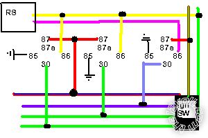
Date Posted: March 05, 2012 at 1:45 PM
This simple:- 5_series.bmp
I've used the original car and R/S colours ------------- Amateurs assume, don't test and have problems; pros test first. I am not a free install service.
Read the installation manual, do a search here or online for your vehicle wiring before posting.
Posted By: mstec
Date Posted: March 05, 2012 at 2:34 PM
howie ll wrote:
Isn't blue/black the starter not ignition?
Sorry not relevant.
Or just 1 output + X no of relays.
E.g. 4 wires = 1 output into 3 relays.
no, starter wire is black\yellow
and
97 BMW 540i has four (4) ignition wires (1x purple and 3x green)
Posted By: howie ll
Date Posted: March 05, 2012 at 3:24 PM
Sorry, we crossed posts, I've already given you the simple answer with that diagram in the last post.
-------------
Amateurs assume, don't test and have problems; pros test first. I am not a free install service.
Read the installation manual, do a search here or online for your vehicle wiring before posting.
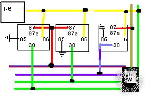
Posted By: howie ll
Date Posted: March 05, 2012 at 3:38 PM
And Bulldog are wrong, don't use the 2nd. ignition to the factory violet, the vehicle won't start, I've just modded my diagram please look.
313_5_series.bmp------------- Amateurs assume, don't test and have problems; pros test first. I am not a free install service.
Read the installation manual, do a search here or online for your vehicle wiring before posting.
Posted By: mstec
Date Posted: March 05, 2012 at 3:43 PM
howie ll wrote:
And Bulldog are wrong, don't use the 2nd. ignition to the factory violet, the vehicle won't start, I've just modded my diagram please look.
313_5_series.bmp
You have 5 ignition wires on your diagram but I have only 4 (1x purple and 3x green) on my ignition switch. What are those two additional wires?
Thanks,
Posted By: mstec
Date Posted: March 05, 2012 at 3:44 PM
mstec] wrote:
howie ll wrote:
And Bulldog are wrong, don't use the 2nd. ignition to the factory violet, the vehicle won't start, I've just modded my diagram please look.
313_5_series.bmp
You have 6 ignition wires on your diagram but I have only 4 (1x purple and 3x green) on my ignition switch. What are those two additional wires?
Thanks,
Posted By: howie ll
Date Posted: March 05, 2012 at 3:48 PM
Sorry,just shut the computer to go to bed, the yellow drives 1 light green directly then EACH OTHER LIGHT GREEN and the VIOLET get 1 relay each.
-------------
Amateurs assume, don't test and have problems; pros test first. I am not a free install service.
Read the installation manual, do a search here or online for your vehicle wiring before posting.
Posted By: howie ll
Date Posted: March 05, 2012 at 3:54 PM
Again sorry, much harder VIA Smartphone, the other 2 are your RED / blue and RED / green 12V+ supply lines, hence my comment about using the car colours in my diagram.
-------------
Amateurs assume, don't test and have problems; pros test first. I am not a free install service.
Read the installation manual, do a search here or online for your vehicle wiring before posting.
Posted By: mstec
Date Posted: March 05, 2012 at 4:01 PM
howie ll wrote:
Again sorry, much harder VIA Smartphone, the other 2 are your RED / blue and RED / green 12V+ supply lines, hence my comment about using the car colours in my diagram.
so, in my case those two additional wires (solid RED) are constand +12v, right?
Good night to you! (we have here 3pm)
Posted By: kreg357
Date Posted: March 05, 2012 at 8:25 PM
mstec] wrote:
ulldog Tech Support just called me back saying:
- Use Ignition#1 (H1/4)(yellow) from RS to TWO (2) green Ignition wires without any relays on 540i
- Use Ignition#2 (H1/5)(Pink) from RS to Purple Ignition wire on 540i
- Use Ignition#3 (H7/1) (Blue/Black) which is a negative using a relay to make it positive to the 3rd green wire on 540i.
What do you guys think about that?
I will definitely try your recommendations first since I like the idea of having everything isolated from each other.
Thanks!
The main problem with the suggestion from Bulldog is combining two 540i Green Ignition wires together. They will no longer be separate isolated circuits, not only during remote start but also during normal vehicle operation. The H1/4 Yellow wire output is probably rated at 20 (or maybe 30 ) Amps and may not be enough for the two ignition circuits demands.
The other problem is, if you use the H7/1 (-) Ignition wire from the Deluxe 500 for a relay for the 4th Ignition circuit and if you need to use H7/1 for the transponder bypass module, you will need some diodes to isolate the relay and the bypass module.
The 540i is a nice car, it's worth the extra effort and cost to do it right the first time.
------------- Soldering is fun!
Posted By: howie ll
Date Posted: March 05, 2012 at 11:59 PM
Please remember that those three greens are all isolated from each other thus you will need the R/S yellow going to one then 3 relays.
One each for the other 2 greens and one for the vehicle violet.
Remember the manufacturer isolates them for a reason, please try to emulate the manufacturer's set-up.
Incidentally assuming key in the box only use a grey valet key.
Why is this thread going on so long.
-------------
Amateurs assume, don't test and have problems; pros test first. I am not a free install service.
Read the installation manual, do a search here or online for your vehicle wiring before posting.
Posted By: howie ll
Date Posted: March 06, 2012 at 12:05 AM
One or two red or RED / green RED / blue = 12V+ input.
3 x light green as ignition 1*.
1 X violet (purple) as ACC wire as ignition 1.
BLACK / YELLOW(? secondary varies)as starter.
*The Euro version gets away with 1 light green. 
Tach, black pin 9 (surprise surprise) on OBD ll data socket or rear of inst. gauges.
DOUBLE check/test everything that Bulldog quotes, it's only a guide and as Kreg has just pointed out in another thread, they've made a mistake on a Saturn's lock polarity. If they can make a mistake on a GM car......... ------------- Amateurs assume, don't test and have problems; pros test first. I am not a free install service.
Read the installation manual, do a search here or online for your vehicle wiring before posting.
Posted By: mstec
Date Posted: March 06, 2012 at 1:03 AM
howie ll wrote:
One or two red or RED / green RED / blue = 12V+ input.
3 x light green as ignition 1*.
1 X violet (purple) as ACC wire as ignition 1.
BLACK / YELLOW(? secondary varies)as starter.
*The Euro version gets away with 1 light green.
Tach, black pin 9 (surprise surprise) on OBD ll data socket or rear of inst. gauges.
DOUBLE check/test everything that Bulldog quotes, it's only a guide and as Kreg has just pointed out in another thread, they've made a mistake on a Saturn's lock polarity. If they can make a mistake on a GM car.........
Alright, I have everything hooked up according your last diagram using only the main ignition output from the RS. I have used 3 relays for the three 540i green ignition wires and the purple from the car straight to the RS (yellow). The car starts now. However it's shuts off after ~19 seconds and starts automatically after ~5 sec. until I turn off the ignition by hand. What can that be?
Thanks a lot for all your help to get it running.
Posted By: howie ll
Date Posted: March 06, 2012 at 2:46 AM
Most likely, tach not correctly programmed.
What by-pass?
Try with key in ignition, if it starts and runs you will know it's the by-pass.
If you have a by-pass which is D2D, run it W2W, up to 2005 on BMW, you're better off hard wiring.
-------------
Amateurs assume, don't test and have problems; pros test first. I am not a free install service.
Read the installation manual, do a search here or online for your vehicle wiring before posting.
Posted By: mstec
Date Posted: March 06, 2012 at 10:47 AM
howie ll wrote:
Most likely, tach not correctly programmed.
What by-pass?
Try with key in ignition, if it starts and runs you will know it's the by-pass.
If you have a by-pass which is D2D, run it W2W, up to 2005 on BMW, you're better off hard wiring.
I went through the steps to program the TACH according the Bulldog Installation Manual. The wire is connected to the back of the inst. gauge black wire on blue plug. Figure it out using BMW wiring diagrams and a DMM.
The transponder bypass module is DesignTech 29402 (EWS III). It is connected to the Bulldog RS but I am not using it yet. The key with the transponder is in ignition "OFF" position. I want to get the car started and running properly first.
Posted By: mstec
Date Posted: March 12, 2012 at 11:28 AM
howie ll wrote:
Most likely, tach not correctly programmed.
What by-pass?
Try with key in ignition, if it starts and runs you will know it's the by-pass.
If you have a by-pass which is D2D, run it W2W, up to 2005 on BMW, you're better off hard wiring.
yes, it was the TACH. I probably did it wrong the first time. I programed the TACH again and it works!  Thank you!
I don't know if is an issue but the engine does not shut off on ignition position two (2), only on position one (1) so I have to turn the key all the way to turn off the car. It's not a big deal but is this normal?
The other thing is the horn output, to get an acoustic confirmation during programming. Does anyone know where to tap the wire to the cars alarm siren other than on the siren it self. I mean somewhere inside the driver compartment.
|