2009 infiniti fx35
Printed From: the12volt.com
Forum Name: Vehicle Wiring Information & File Requests
Forum Discription: Request Car Alarm, Car Stereo, Cruise Control, Remote Starter, Navigation, Mobile Video, and Other Vehicle Specific Wiring Info, Manuals, Tech Tips
URL: https://www.the12volt.com/installbay/forum_posts.asp?tid=131213
Printed Date: February 15, 2026 at 12:36 AM
Topic: 2009 infiniti fx35
Posted By: twashi43
Subject: 2009 infiniti fx35
Date Posted: April 18, 2012 at 3:15 AM
Anyone have any info on wiring a Viper 5904 alarm remote start on a 2009 Fx35 and pkall bypass?
Replies:
Posted By: kreg357
Date Posted: April 18, 2012 at 6:57 AM
Here is a link to the FX35 wiring info from DEI :
https://www.readyremote.com/main.asp?make=Infiniti&model=FX35
I don't see the PKALL listed for the 2009 FX35. Think you would be much
happier with the EVO-ALL. Here is a link for the EVO-ALL bypass install :
https://ifar.ca/download/3909/preview.html
------------- Soldering is fun!
Posted By: twashi43
Date Posted: April 18, 2012 at 10:25 AM
Thank you so much!
BTW pkall bypass was my mistake,I meant DBALL Xpresskit.
Posted By: twashi43
Date Posted: April 19, 2012 at 10:21 PM
kreg357 wrote:
Here is a link to the FX35 wiring info from DEI :
https://www.readyremote.com/main.asp?make=Infiniti&model=FX35
I don't see the PKALL listed for the 2009 FX35. Think you would be much
happier with the EVO-ALL. Here is a link for the EVO-ALL bypass install :
https://ifar.ca/download/3909/preview.html
Almost everything is wired up and working,except the remote start.This vehicle has 2of everything,2 starter wires,2 ignition wires,and 2 accessory wires.Also I know in the past you normally cut the starter wire for the starter kill.Here are the wires:
Starter lt.blue (push-button start) - push-button ignition switch or BCM, black 40 pin plug, pin 18
Second Starter lt. green - BCM, gray 40 pin plug, pin 21
Ignition pink + BCM, black 40 pin plug, pin 11
Second Ignition yellow - BCM, gray 40 pin plug, pin 16
Accessory orange + BCM, black 40 pin plug, pin 31
Second Accessory orange + BCM, black 40 pin plug, pin 24
Posted By: twashi43
Date Posted: April 19, 2012 at 11:09 PM
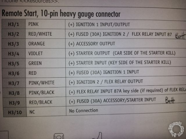
This is the Viper 10 pin starter harness:
Posted By: howie ll
Date Posted: April 20, 2012 at 3:40 AM
Only cut starter 1, violet to key side and green to starter.
Program the pink/white as second starter.
Power up all three of red, RED / black and RED / white.
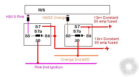
Now look at H2 and with 2 relays and 4 x 1N4004 diodes:-
2nd_ignition_and_acc.bmp------------- Amateurs assume, don't test and have problems; pros test first. I am not a free install service.
Read the installation manual, do a search here or online for your vehicle wiring before posting.
Posted By: twashi43
Date Posted: April 21, 2012 at 12:24 PM
howie ll wrote:
Only cut starter 1, violet to key side and green to starter.
Program the pink/white as second starter.
Power up all three of red, RED / black and RED / white.
Now look at H2 and with 2 relays and 4 x 1N4004 diodes:-
2nd_ignition_and_acc.bmp
Ok correct me if I'm wrong on the 2 relays which are both the same.Should look like this: 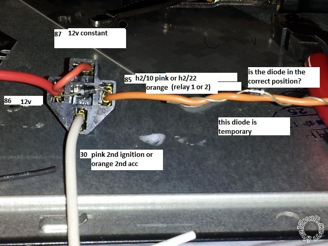
Posted By: howie ll
Date Posted: April 21, 2012 at 1:55 PM
First I made an error, it's GREEN to key side and VIOLET to starter side. 
The right hand temp diode is correct just cut the orange and pink and mount the diode in line. Your band position on both is correct. ------------- Amateurs assume, don't test and have problems; pros test first. I am not a free install service.
Read the installation manual, do a search here or online for your vehicle wiring before posting.
Posted By: twashi43
Date Posted: April 21, 2012 at 2:40 PM
Thanks,I am about to wire it in the Fx.
Posted By: twashi43
Date Posted: April 21, 2012 at 9:14 PM
howie ll wrote:
First I made an error, it's GREEN to key side and VIOLET to starter side.
The right hand temp diode is correct just cut the orange and pink and mount the diode in line. Your band position on both is correct.
I did a test on the relays and something seems to be wrong,I am getting constant 12 volts on 85 and it will make the alarm non functional.
Posted By: howie ll
Date Posted: April 22, 2012 at 1:32 AM
Try applying a negative pulse (ground) to the 85 side, you should then get a POS output at 30.
-------------
Amateurs assume, don't test and have problems; pros test first. I am not a free install service.
Read the installation manual, do a search here or online for your vehicle wiring before posting.
Posted By: howie ll
Date Posted: April 22, 2012 at 5:18 AM
I just set up a relay in exactly the same way too much testing, not enough installing.
You will show NEG on 85, it's coming back through the coil.
As soon as you apply a ground, all will be OK.
But now you see one reason for the diodes don't you.
-------------
Amateurs assume, don't test and have problems; pros test first. I am not a free install service.
Read the installation manual, do a search here or online for your vehicle wiring before posting.
Posted By: twashi43
Date Posted: April 22, 2012 at 10:21 AM
Ok this is my set up:
Starter lt.blue (push-button start) (-) push-button ignition switch or BCM, black 40 pin plug, pin 18
Second Starter lt. green (-) BCM, gray 40 pin plug, pin 21
Ignition pink (+) BCM, black 40 pin plug, pin 11
Second Ignition yellow (-) BCM, gray 40 pin plug, pin 16
Accessory orange (+) BCM, black 40 pin plug, pin 31
Second Accessory orange (+) BCM, black 40 pin plug, pin 24
The neg(-)at 85 should be a body ground? And where would I put the (h1)pink ignition wire or should this be h2/2 BLACK/ white neutral safety input?
Posted By: kreg357
Date Posted: April 22, 2012 at 12:54 PM
I'm a little confused with this install. You have a 2009 Infinity FX35 with
Push To Start, a Viper 5904 and a DB-ALL flashed with 401.NISS03 v2.00 firmware.
The DB-ALL would be installed following the Type 1 diagram. Program the DB-ALL
for Option 2 Door Locks and Parking Light control.
Using a Viper 5904, the only relay required is under the hood at the IPDM box.
The wiring for the relay is shown on Page 5 of the install guide. The 5904 is
capable of supplying all the other "ignition signals" directly to the BCM without
the need for any additional relays. Connections listed on Page 5 of the DB-ALL
install guide ( from box on Page 4 ).
(-) Starter Out to BCM Gray connector Pin 21 comes from Viper H2/18 Violet / YELLOW
(-) Ignition 2 Out to BCR Gray connector Pin 16 comes from Viper H2/10 Pink
(+) Accessory Out to BCM Black connector Pins 24 & 31 comes from Viper H3/3 and
is split with diodes as shown.
(+) Ignition 1 Out to BCM Black connector Pin 11 comes from Viper H3/1 Pink
The Viper Flex relay output H3/7 can be programmed as (+) Accessory 2 ( Menu 3,
Item 8, Opt 2 ) and can be connected as shown if the A/C does not work during a
remote start.
The Starter Light Blue PTS wire listed in the chart is not shown in the install
diagrams, so I am not sure which Viper or DB-ALL wire would connect to it, if any.
Assuming your FX35 is an automatic trans vehicle and you are using the D2D harness
between the Viper and the DB-ALL, the Vipers' Neutral Safety wire is "D2D connected"
to (-) EBrake signal from the DB-ALL as shown in the Type 1 diagram using a dashed
Blue line. ------------- Soldering is fun!
Posted By: twashi43
Date Posted: April 22, 2012 at 1:43 PM
I didn't know what wires to connect from the bcm to the alarm(viper 5904). I looked at the size of the wires in the bcm and that threw me off.I am used to the (older heaver gauge wire) key style,like in my 1997 or my 2004 Maxima.I ordered the DB-ALL off line and it was shipped with the wrong instructions and the wrong firmware(Niss02).I am going down now to flash it with (401.NISS03 v2.00 firmware).Will give it another shot when the rain stops.Thanks again for everything,sorry for the confusion.
Posted By: kreg357
Date Posted: April 22, 2012 at 2:35 PM
Yes, the new Nissans / Infinitys are somewhat different and slightly more complicated than the older vehicles, especially with PTS and SmartKey. All the wires at the BCM are thin gauge and some of the Vipers heavy gauge H3 wires get connected to them. The hardest part is getting that relay into the IPDM box neatly. Also, use a sealed ( weather tight ) relay if you have one available.
The new Fortin EVO-ALL bypass module makes this install a lot easier... ------------- Soldering is fun!
Posted By: twashi43
Date Posted: April 23, 2012 at 9:21 PM
[QUOTE=kreg357] Yes, the new Nissans / Infinitys are somewhat different and slightly more complicated than the older vehicles, especially with PTS and SmartKey. All the wires at the BCM are thin gauge and some of the Vipers heavy gauge H3 wires get connected to them. The hardest part is getting that relay into the IPDM box neatly. Also, use a sealed ( weather tight ) relay if you have one available.
The new Fortin EVO-ALL bypass module makes this install a lot easier... [/QUOTE
Mission accomplished!I want to thank you,kreg357 and howwie for all your input ------------- I may be new to this,but I am true to this
Posted By: kreg357
Date Posted: April 24, 2012 at 7:25 AM
Excellent! Good job!  ------------- Soldering is fun!
|