2007 hummer h2 viper 5704
Printed From: the12volt.com
Forum Name: Vehicle Wiring Information & File Requests
Forum Discription: Request Car Alarm, Car Stereo, Cruise Control, Remote Starter, Navigation, Mobile Video, and Other Vehicle Specific Wiring Info, Manuals, Tech Tips
URL: https://www.the12volt.com/installbay/forum_posts.asp?tid=132709
Printed Date: April 19, 2026 at 1:40 AM
Topic: 2007 hummer h2 viper 5704
Posted By: 07h2
Subject: 2007 hummer h2 viper 5704
Date Posted: November 18, 2012 at 11:38 PM
Hi everyone,
I'm a rookie when it comes to 12 volt, but atleast I'm trying. Anyways I have a Viper 5704 w/ 5904( 2way) remote and Idatalink ADS AL CA. Vehicle is a 2007 Hummer H2.
I'm looking for any help pics, comments, tips, suggestions to verify I have done the intall correctly.
So far what I have accomplished, the alarm and basic wiing is hooked up. I am able to get a solid led from the control antanne, but thats all. When I try and get it in to program mode the siren will not chirp nor will the control antanne led flash.
When I hold down the arm button on the remote (1 way ) the siren chirps however the doors do not lock. Also when I hold down the disarm button on the one way remote the siren does not chirp and the doors also do not unlock.
Once again any help would be greatly appreciated.
Thanks
Replies:
Posted By: shortcircuit161
Date Posted: November 19, 2012 at 8:11 AM
Did you flash the correct firmware on the ADS-AL for your vehicle? Did you follow the programming steps once installed in the Hummer?
There is also a lot of info on this vehicle in the forum if you search it.
The viper manual will tell you why you have a solid LED on the antenna.
-------------
Posted By: 07h2
Date Posted: November 19, 2012 at 8:55 AM
Thanks for the quick reply,
No i didnt flash the ads al. Ill try and get that done and post a update as soon as possible.
Posted By: 07h2
Date Posted: November 19, 2012 at 5:17 PM
07h2] wrote:
Thanks for the quick reply,
No i didnt flash the ads al. Ill try and get that done and post a update as soon as possible.
Just ordered the weblink will bew a few weeks before it shows up. Ill update as I go along.
Posted By: 07h2
Date Posted: November 21, 2012 at 2:08 AM
Its gonna be a couple of weeks before I can get the module flashed so I decided to do some homework.
I found this on another thread and was wondering if it applied
Try this:
Viper H3/ Yukon
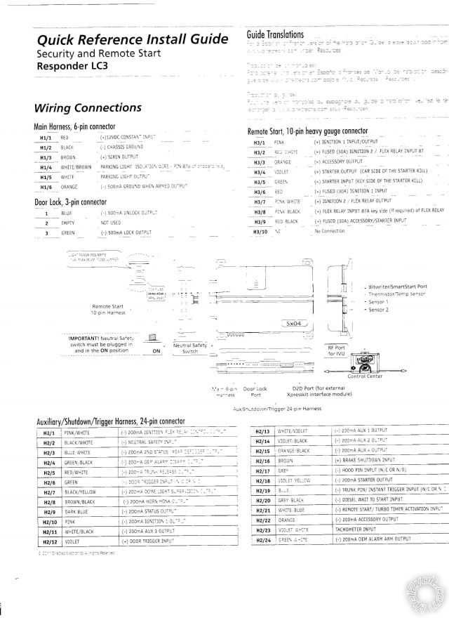
1.Pink (+)Ignition 1 Input/Output - Pink wire, shows +12V in run and start positions
2.RED / White (87) Flex (30A Fused) - Red @ Ignition Switch Harness
3.Orange (+)Accessory Output - Orange wire, shows +12V in run but not start position
4.Violet (+)Starter Output (Car Side Of Starter Kill) - Starter side of purple wire (cut), shows +12V in start position
5.Green (+)Starter Input (Key Side Of Starter Kill) - Ignition switch side of above purple wire
6.Red Ignition 1 Input (30A Fused) - Red @ Ignition Switch Harness
7.Pink/White (30) Flex Relay Output - White @ Ignition Switch Harness ***Viper Menu 3, Item 8, Opt 1
8.Pink/Black (87a) Flex Relay Input - NC
9.RED / Black Acc/Starter (30A Fused) - Red @ Ignition Switch Harness
10.No Connection
Brown ACC2 wire at ignition switch harness requires extra 30/40A SPDT relay :
Pin 85 to Viper Orange (-)200mA Accessory2 Output
Pin 86 and 87 to +12V Constant thru 20A fuse
Pin 30 to Brown ACC2 @ Ignition Switch Harness
Pin 87A not used - insulate
Posted By: 07h2
Date Posted: November 21, 2012 at 2:22 AM
on the h2 aux/shutdown/trigger harness which connections can I omit?
h2/1 (-)200ma ignition/flex relay control output
h2/2 (-) Neutral Safety input
h2/3 (-) 200ma 2nd status/rear defogger output
h2/4 (-) 200ma oem alarm disarm output
h2/5 (-) 200ma trunk release output
h2/6 (-) door trigger input (n/c or n/o)
h2/7 (-) 200ma dome light supervision output
h2/8 (-) 200ma horn honk output
h2/9 (-) 200ma status output
h2/10 (-) 200ma ignition 1 output
h2/11 (-) 200ma aux 3 output
h2/12 (-) door trigger input
h2/13 (-) 200ma aux 1 output
h2/14 (-) 200ma aux 2 output
h2/15 (-) 200ma aux 4 output
h2/16 (+) brake shutdown input
h2/17 (-) hood pin input (n/c or n/o)
h2/18 (-) 200ma starter output
h2/19 (-) trunk pin/ instant trigger input (n/c or n/o)
h2/20 (-) diesel wait to start input
h2/21 (-) remote start/turbo timer activation input
h2/22 (-) 200ma accessory input
h2/23 tachometer input
h2/24 (-) 200ma oem alarm arm out put
Posted By: 07h2
Date Posted: November 21, 2012 at 2:26 AM
on the main harness of the viper does
h1/6 (-)500ma ground when armed output
get connected to anything?
Posted By: 07h2
Date Posted: November 21, 2012 at 2:28 AM
the more i read the more i question my install, going to remove and redo everything for a more cleaner install and plan on taking pics to upload.
Posted By: 07h2
Date Posted: November 21, 2012 at 2:38 AM
Posted By: kreg357
Date Posted: November 21, 2012 at 6:19 AM
A few thoughts / updates...
Besides the ADS USB cable, you must register on the Flash section of the iDatalink WEB site and
pass their requirements to be able to use the ADS USB cable and re-program any bypass module.
Additionally you can flash the ADS or the DBI flavor of firmware on to the module. With the
ADS version, you must connect the bypass to the Viper in W2W mode. With the DBI version you
could go D2D. ( I don't use too many Viper systems so I can comment on how well DBI D2D works.)
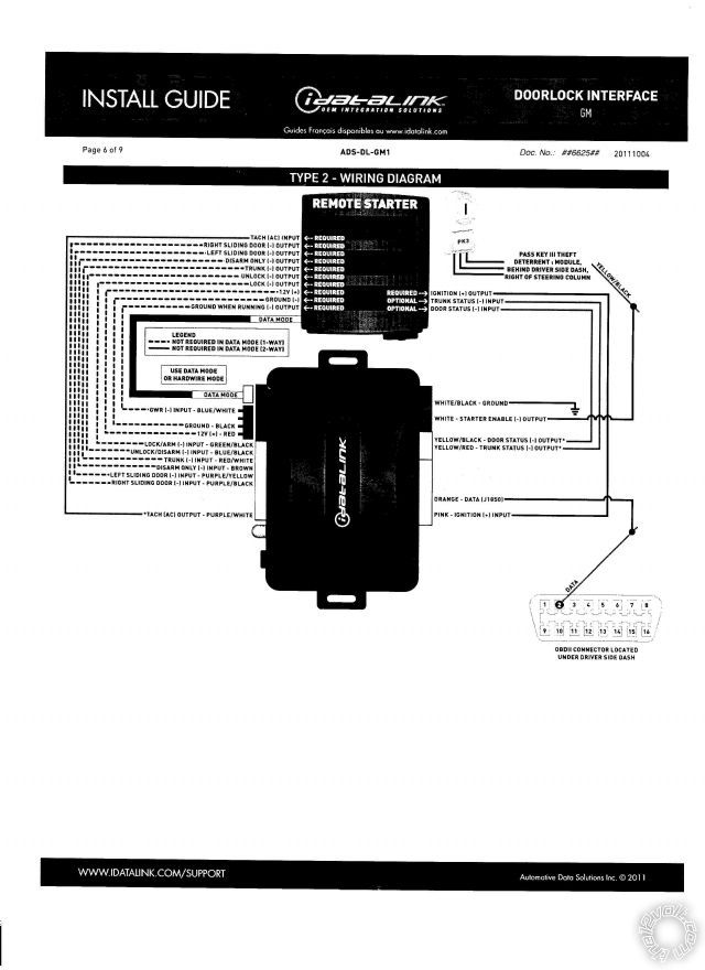
The correct firmware for your ADS AL CA is ADS AL(DL) GM1 using install guide #6611 and the
Type 3 install diagram. If you decide to use DBI firmware and go D2D, the correct firmware
is DBI AL(DL) GM1. Here is a link to the iDatalink WEB site : https://www.idatalink.com/support
This H3 wiring will work on your 2007 H2 with this correction to the Starter wire color.
1.Pink (+)Ignition 1 Input/Output - Pink wire @ Ignition Switch Harness
2.RED / White (87) Flex (30A Fused) - Red @ Ignition Switch Harness
3.Orange (+)Accessory Output - Orange wire @ Ignition Switch Harness
4.Violet (+)Starter Output (Car Side) - Starter side of (cut) Yellow wire @ Ignition Switch Harness
5.Green (+)Starter Input (Key Side) - Ignition switch side of above (cut) Yellow wire @ Ignition Switch Harness
6.Red Ignition 1 Input (30A Fused) - Red @ Ignition Switch Harness
7.Pink/White (30) Flex Relay Output - White @ Ignition Switch Harness ***Viper Menu 3, Item 8, Opt 1
8.Pink/Black (87a) Flex Relay Input - NC
9.RED / Black Acc/Starter (30A Fused) - Red @ Ignition Switch Harness
10.No Connection
Brown ACC2 wire at ignition switch harness requires extra 30/40A SPDT relay :
Pin 85 to Viper H2/22 Orange (-)200mA Accessory2 Output
Pin 86 and 87 to +12V Constant thru 20A fuse
Pin 30 to Brown ACC2 @ Ignition Switch Harness
Pin 87A not used - insulate
As for unused and necessary H2 connections :
h2/1 (-)200ma ignition/flex relay control output N.U.
h2/2 (-) Neutral Safety input Chassis Ground
h2/3 (-) 200ma 2nd status/rear defogger output N.U.
h2/4 (-) 200ma oem alarm disarm output N.U.
h2/5 (-) 200ma trunk release output N.U.
h2/6 (-) door trigger input (n/c or n/o) To ADS Door Status output ( only covers front doors )
h2/7 (-) 200ma dome light supervision output N.U.
h2/8 (-) 200ma horn honk output Optional
h2/9 (-) 200ma status output To ADS GRW in W2W mode
h2/10 (-) 200ma ignition 1 output N.U.
h2/11 (-) 200ma aux 3 output N.U.
h2/12 (-) door trigger input To ADS Door Status Output in W2W mode
h2/13 (-) 200ma aux 1 output N.U.
h2/14 (-) 200ma aux 2 output N.U.
h2/15 (-) 200ma aux 4 output N.U.
h2/16 (+) brake shutdown input To ADS Brake output in W2W mode
h2/17 (-) hood pin input (n/c or n/o) To supplied hood pin switch ( N.C. )
h2/18 (-) 200ma starter output N.U.
h2/19 (-) trunk pin/ instant trigger input (n/c or n/o) To ADS Trunk Status output in W2W mode
h2/20 (-) diesel wait to start input N.U.
h2/21 (-) remote start/turbo timer activation input N.U.
h2/22 (-) 200ma accessory input To extra relay
h2/23 tachometer input To ADS Tach output ***Set Viper to Tach Mode, Menu 3, Item 2, Opt 4
h2/24 (-) 200ma oem alarm arm out put N.U.
Here is Viper's info on H1/6 GWA :
This wire supplies a (-)500 mA ground as long as the system is armed. This output
ceases as soon as the system is disarmed. The GWA can be hooked up to a
window control module, a voice module or any accessory that requires a ground
when armed.
It can also be used with programming option 3-13 to provide the Anti-Grind feature. Viper info below :
3-13 ANTI-GRIND ON: With the anti-grind On (default) the ground-when-armed
output will be active during remote start operation. This activates the starter
kill relay and prevents the customer from re-cranking the car with the key, when
doing key takeover. If accessories such as a voice module or window module are
added to the unit, it may be necessary to use the two-chirp setting to program
this feature OFF.
Re - re-doing install :
This is a fairly easy install with the ADS bypass module. It does most everything for you. I would mate the Viper to the
properly flashed ADS AL CA bypass module in W2W mode on the bench, prior to vehicle install. Solder all connections
and use heat shrink tube where ever possible. The only gotcha is the rear door pins. To do it correctly you will
need some diodes ( 1N400x ). Here is the info from Ready Remote :
The driver door trigger is gray/black (-) at the driver door module in the door. The RF door trigger is BLACK/ white (-)
at the passenger door module in the door. The LR door trigger is lt. blue/black (-), pin A3, and the RR is lt. GREEN/ black (-),
pin A2, they are in the purple plug at the BCM. Use all four wires and diode isolate each.
The BCM (Body Control Module) is located behind the headlight switch. It has 6 plugs in it, the purple plug is on the back.
The ADS bypass module supplies the front door triggers as previously mentioned. You will need to diode isolate the two
rear door status wires from the truck and join them into the Vipers H2/6 Green (-) Door Trigger input which already has
the ADS (-) Door Status Output.
As always, use your DMM to locate and verify all vehicle wires ( except OBD2 Data ). ------------- Soldering is fun!
Posted By: 07h2
Date Posted: November 21, 2012 at 11:20 AM
Thanks for the reply, very informative. What requirements are needed to flash the module?
Posted By: tommy...
Date Posted: November 21, 2012 at 11:30 AM
07h2] wrote:
Thanks for the reply, very informative. What requirements are needed to flash the module?
https://www.idatalink.com/weblink5/ ------------- M.E.C.P & First-Class
Go slow and drink lots of water...Procrastinators' Unite...Tomorrow!
Posted By: kreg357
Date Posted: November 21, 2012 at 11:30 AM
Here is a link to the iDatalink registration form : https://www.idatalink.com/weblink5/user/registration------------- Soldering is fun!
Posted By: kreg357
Date Posted: November 21, 2012 at 11:32 AM
Simultaneous answers !!!  The 12Volt is awesome! ------------- Soldering is fun!
Posted By: 07h2
Date Posted: November 21, 2012 at 9:39 PM
Here is Viper's info on H1/6 GWA :
This wire supplies a (-)500 mA ground as long as the system is armed. This output
ceases as soon as the system is disarmed. The GWA can be hooked up to a
window control module, a voice module or any accessory that requires a ground
when armed.
Sorry but I'm confused on where I can hook up the GWA.
Posted By: kreg357
Date Posted: November 22, 2012 at 6:35 AM
On a basic installation, the H1/6 GWA wire is not used.
If you feel you must use it, the easiest, least time consuming and inexpensive way is to connect it to a DEI 629L light ( or similar scanning LED light assy ). ------------- Soldering is fun!
Posted By: 07h2
Date Posted: November 30, 2012 at 5:13 AM
Can ifet mire details about the relay installed for the brown acc wire. Why are only three pins used and two of them are 12 v constant ?
Posted By: 07h2
Date Posted: November 30, 2012 at 5:14 AM
* can i get more details
Posted By: kreg357
Date Posted: November 30, 2012 at 5:45 AM
Actually 4 relay pins have connections. Here are the relay operation details :
Under normal conditions, the un-energized relay will have a connection between pins 30 and
87A ( marked N.C. for normally closed ). Relay Pins 85 and 86 are used to energize the relays
coil. Standard convention has Pin 85 being (-) and Pin 86 being (+). To energize this relay,
we connect Pin 86 to a constant +12V and Pin 85 to the Vipers (-) Accessory control signal. So
when the Viper outputs the (-) Accessory signal the relay will energize and switch to the N.O.
wire ( normally open ), making a connection from Pin 30 to Pin 87, and opening the connection
between Pin 30 and 87A.
So, with no Viper (-) Accessory output, the relay is internally connected Pin 30 to 87A and
supplies nothing out Pin 30 to the vehicles Brown Accessory2 wire. When the Viper outputs
the (-) Accessory signal, the relays coil energizes and internally the Pin 30 contact switches
from Pin 87a to Pin 87. Pin 87 is connected to +12V constant power and allows relay Pin 30
to supply the vehicles Brown ACC2 wire with power.
Brown ACC2 wire at ignition switch harness requires extra 30/40A SPDT relay :
Pin 85 to Viper H2/22 Orange (-)200mA Accessory2 Output
Pin 86 and 87 to +12V Constant thru 20A fuse
Pin 30 to Brown ACC2 @ Ignition Switch Harness
Pin 87A not used - insulate
The 12Volt has a very good write-up / explanation on relays too. Here is the link : https://www.the12volt.com/relays/relays.asp ------------- Soldering is fun!
Posted By: 07h2
Date Posted: December 12, 2012 at 12:10 AM
Which of the inputs on the idatalink are not used ?
Posted By: 07h2
Date Posted: December 12, 2012 at 11:21 AM
*in w2w mode
Posted By: kreg357
Date Posted: December 12, 2012 at 6:27 PM
Here is a link to the ADS AL CA flashed with ADS AL(DL) GM1 firmware install guide :
https://www.idatalink.com/support/get-install-guide/guide_id/6614 This is the correct
firmware for your 2007 H2 when using the ADS AL CA module.
Follow the Type 3 install diagram for you 2007 H2. You will run all the wires shown with
the exception of the Trunk Release, Left and Right Sliding Door wires. They are not
applicable to your vehicle. Additionally the ADS Door Status Output will only supply
the front doors. To monitor the rear doors see the info previously supplied. ------------- Soldering is fun!
Posted By: 07h2
Date Posted: December 12, 2012 at 7:59 PM
I've decided to go with the d2d setup.
Everything is hookep up. I'm having difficulties programong the viper alarm, idatalink and pairing the 2way remote. 1 way appears to be paired. When i arm and disarm from the 1 way i get a chirp and led on control center flashes consistently. I am unable to put the viper into pairing mode for tge two way. No matter which way i try it wont flash or chirp to say the system is ready for pairing.
Posted By: 07h2
Date Posted: December 12, 2012 at 8:24 PM
I have the right firmware DBI-AL(DL)-GM1(v4.4)
Posted By: 07h2
Date Posted: December 12, 2012 at 8:29 PM
*v4.8
Posted By: 07h2
Date Posted: December 12, 2012 at 8:56 PM
also the idatalink flashes green and when I turn the car over it doesnt flash until the car has finished cracking and started. When I push the remote start button on the one way I can hear the relay clicking but no action otherwise.
Posted By: 07h2
Date Posted: December 12, 2012 at 10:27 PM
doubled checked all connections, everything looks good. First I'm working on how to pair the remote. I can't seem to get the control center to engage pairing mode. Tried power cycling which didn't change anything.
Even with the idatalink not hookedup I should still be able to pair the remote with the viper unit?
Posted By: 07h2
Date Posted: December 13, 2012 at 12:00 AM
also let me add that I can still start the truck with the key, with out any problems
Posted By: howie ll
Date Posted: December 13, 2012 at 1:35 AM
Tip. Temporarily ground the green H2/6 wire.
-------------
Amateurs assume, don't test and have problems; pros test first. I am not a free install service.
Read the installation manual, do a search here or online for your vehicle wiring before posting.
Posted By: 07h2
Date Posted: December 13, 2012 at 10:17 AM
Grounding the h2/6 has lead to some success. I was able to get tge alarm to engage in the programming mode.
Posted By: howie ll
Date Posted: December 13, 2012 at 10:20 AM
That means your door trigger at present isn't connected.
-------------
Amateurs assume, don't test and have problems; pros test first. I am not a free install service.
Read the installation manual, do a search here or online for your vehicle wiring before posting.
Posted By: 07h2
Date Posted: December 13, 2012 at 10:30 AM
But still unable to program the 2 way
Posted By: howie ll
Date Posted: December 13, 2012 at 11:05 AM
Is the 2 way charged?
Is the battery solidly in?
Do you have to program it to the R/S?
-------------
Amateurs assume, don't test and have problems; pros test first. I am not a free install service.
Read the installation manual, do a search here or online for your vehicle wiring before posting.
Posted By: 07h2
Date Posted: December 13, 2012 at 11:21 AM
Yes 2 way fully charged, yes battery in, yes i need to program it to remote start and fully functional alarm.
Posted By: 07h2
Date Posted: December 13, 2012 at 11:27 AM
Im pulling the d2d out and trying w2w.
On the idatalink to viper im confused
Idatalink. Viper
Tach. Tach
Right s.d. ?
Left s.d. ?
Disarm. ?
Trunk in. ?
Unlock in. ?
Lock in. ?
Posted By: 07h2
Date Posted: December 13, 2012 at 12:01 PM
Im going through everything here
H1/1 - 12vdc
H1/2 - ground
H1/3 - siren
H1/4 - n/c
H1/5 - n/c
H1/6 - n/c
Door lock 3-pin
1- n/c
2 - n/c
3 -n/c
Aux/shutdown
H2/1 - n/c
H2/2 - ground
H2/3 - n/c
H2/4 - n/c
H2/5 - n/c
H2/6 - door status output (-) idatalink
H2/7 - n/c
H2/8 - n/c
H2/9 - gwr (-) input idatalink
H2/10 - n/c
H2/11 - n/c
H2/12 - n/c
H2/13 - n/c
H2/14 - n/c
H2/15 - n/c
H2/16 - n/c
H2/17 - hood pin
H2/18 - n/c
H2/19 - trunk status (-) input idatalink
H2/20 - n/c
H2/21 - n/c
H2/22 - relay pin 30 spdt
H2/23 - tach ac output idatalink
H2/24 - n/c
H3/1 - pink ignition
H3/2 - RED / white pin 86 spdt
H3/3 - orange ignition
H3/4- yellow car side
H3/5 - yellow key side
H3/6 - red ignition
H3/7 - white ignition
H3/8 - n/c
H3/9 - red ignition
H3/10 - n/c
Posted By: shortcircuit161
Date Posted: December 13, 2012 at 12:19 PM
You should be able to pair the remotes regardless of having a bypass module connected to it or not.
Make sure that door trigger wire is grounded prior to turning the ignition switch on.
Turn the ignition switch on and keep it on before attempting to pair any remotes (unlike programming features where you would turn the key on, then off). Then go thru the pairing process and keep fingers crossed.
Did the 2-way remote come with that system? Or did you buy it separately to add-on to this system?
-------------
Posted By: 07h2
Date Posted: December 13, 2012 at 12:22 PM
*h2/25- pin 85 relay
Relay
85 - h2/25
86 & 87 12v
30 brown acc ignition
Posted By: 07h2
Date Posted: December 13, 2012 at 12:26 PM
The two way was purchased seperatley as an upgraded feature.
7941v on viper website shows compatibilty with 5704v
Posted By: howie ll
Date Posted: December 13, 2012 at 12:35 PM
There is NO H2/25, it's a 24 pin plug.
Did you mean H2/22?
-------------
Amateurs assume, don't test and have problems; pros test first. I am not a free install service.
Read the installation manual, do a search here or online for your vehicle wiring before posting.
Posted By: 07h2
Date Posted: December 13, 2012 at 12:37 PM
**h2/22 - pin 85
Posted By: howie ll
Date Posted: December 13, 2012 at 4:33 PM
Diode the relay, 1N4004, band towards 86.
-------------
Amateurs assume, don't test and have problems; pros test first. I am not a free install service.
Read the installation manual, do a search here or online for your vehicle wiring before posting.
Posted By: 07h2
Date Posted: December 13, 2012 at 5:42 PM
Could you please explain the purpose of diode 86.
Thanks
Posted By: howie ll
Date Posted: December 13, 2012 at 6:19 PM
When relays shut down they "spike", an EMP from the coil of about 200volts.
Without that coil relay and possibly a second on H2/22, band towards the R/S you WILL DESTROY YOUR R/S.
I believe the instructions mention this, they used to on the 5901.
-------------
Amateurs assume, don't test and have problems; pros test first. I am not a free install service.
Read the installation manual, do a search here or online for your vehicle wiring before posting.
|