1995 celica remote starter
Printed From: the12volt.com
Forum Name: Vehicle Wiring Information & File Requests
Forum Discription: Request Car Alarm, Car Stereo, Cruise Control, Remote Starter, Navigation, Mobile Video, and Other Vehicle Specific Wiring Info, Manuals, Tech Tips
URL: https://www.the12volt.com/installbay/forum_posts.asp?tid=133289
Printed Date: May 03, 2026 at 10:32 AM
Topic: 1995 celica remote starter
Posted By: doory100
Subject: 1995 celica remote starter
Date Posted: January 13, 2013 at 9:32 AM
Wiring diagram and procedure/tips I should know about for a 1995 toyota celica liftback gts. for remote start and keyless entry? Thank you.
-------------
McFly
Replies:
Posted By: kreg357
Date Posted: January 13, 2013 at 3:24 PM
For vehicle wiring, here are some sources :
Here is a link to Bulldog Security : https://www.bulldogsecurity.com/bdnew/vehiclewiringdiagrams.asp
Here is a link to Ready Remote : https://www.readyremote.com/main.asp
Here is a link to AudioVox : https://techservices.audiovox.com/AccessRequest.aspx Sign-up & info is free. ------------- Soldering is fun!
Posted By: doory100
Date Posted: January 13, 2013 at 3:44 PM
I have a pro start 2way starter.  ------------- McFly
Posted By: kreg357
Date Posted: January 13, 2013 at 4:08 PM
You can find more info on the ProStart system at : https://www.autostart.ca/prostart/prod-en_CT-3300.php
Can't help too much with the ProStart as it is not my usual brand.
Download all available wire guide listings and make up a cheat sheet using the ProStart's harnesses. Post that for forum input. ------------- Soldering is fun!
Posted By: doory100
Date Posted: February 04, 2013 at 11:24 AM
I have a questions about installing the starter: what do I do with the second ignition wire?
-------------
McFly
Posted By: howie ll
Date Posted: February 04, 2013 at 3:13 PM
Too easy, I just looked at the diagram.
You have jumpers one side, move the one marked second ignition, that's your green wire.
-------------
Amateurs assume, don't test and have problems; pros test first. I am not a free install service.
Read the installation manual, do a search here or online for your vehicle wiring before posting.
Posted By: doory100
Date Posted: February 04, 2013 at 4:10 PM
I'm not to sure I follow you? What green wire? The jumpers are on the second ignition by default. My car has a second ignition. But I don't need to hook that up to the starter at all. Right?
-------------
McFly
Posted By: howie ll
Date Posted: February 04, 2013 at 5:17 PM
Nope, you connect that as the second ignition, I believe that was your question,
so that's your answer.
-------------
Amateurs assume, don't test and have problems; pros test first. I am not a free install service.
Read the installation manual, do a search here or online for your vehicle wiring before posting.
Posted By: doory100
Date Posted: February 04, 2013 at 6:56 PM
https://www.engines911.com/asdocs/CT-3471_wd_en_h51s41_110609.pdf
so let me get this right, the green 5th relay wire (image above) connects to the second ignition and i make sure the jumper is on the ignition 2 conecters on the back and thats should make it work now?
-------------
McFly
Posted By: kreg357
Date Posted: February 04, 2013 at 8:05 PM
Like this...
R/S thick wires Function 1995 Celica
Yellow IGN1 BLACK/ Orange @ ignition switch harness
Red +12V White @ ignition switch harness
Orange ACC1 Gray @ ignition switch harness
Purple Starter1 BLACK/ White @ ignition switch harness
Green 5th Relay Blue/Red @ ignition switch harness ***Set jumper to IGN2
Red +12V BLACK/ Red @ ignition switch harness ------------- Soldering is fun!
Posted By: doory100
Date Posted: February 04, 2013 at 8:57 PM
Thanks also the black ground (-) what wire does that connect to. Also the white (-) ground when running wire connects to which wire? I have all the other wires finished. This is great help!!
-------------
McFly
Posted By: kreg357
Date Posted: February 05, 2013 at 3:07 AM
The R/S's Black Ground wire should have a terminal ring soldered on it. Then it should be connected
to a paint / rust free area of the vehicles solid metal chassis. The best locations are a factory bolt or
screw that attaches metal pieces to solid frame. Here is a picture of a nice bolt in a convenient location
on an Impala. The gold colored bolt in the door jam / dash side access panel.
For your 1995 Celica install, the White GWR wire is not used. It is typically used to control a bypass
module, which your car does not require. ------------- Soldering is fun!
Posted By: doory100
Date Posted: February 05, 2013 at 6:05 AM
Thanks for your help
-------------
McFly
Posted By: doory100
Date Posted: February 14, 2013 at 10:39 PM
How do I bypass my clutch?
-------------
McFly
Posted By: howie ll
Date Posted: February 15, 2013 at 3:12 AM
You or me Kregg?
Since I have no info I'll tell you the safe method.
Somewhere at the top of the clutch pedal support should be a switch that looks like a brake switch.
It should have two wires.
Using your DMM set to continuity, probe into each.
Is there continuity? If so you have to "open" the circuit.
More likely you only get continuity when you depress the clutch.
If the second case see diagram:- clutch_switch_2.bmp
You will need a four terminal relay (5 will do, just don't use terminal 87a) and a 1N4004 diode.
The next method will be explained by Kregg but for any further testing the VEHICLE MUST NOT BE LEFT IN GEAR.------------- Amateurs assume, don't test and have problems; pros test first. I am not a free install service.
Read the installation manual, do a search here or online for your vehicle wiring before posting.
Posted By: doory100
Date Posted: February 15, 2013 at 9:05 AM
What is the RS wire I use called?
-------------
McFly
Posted By: howie ll
Date Posted: February 15, 2013 at 9:12 AM
And the answer is...." Also the white (-) ground when running wire connects to which wire? "
Come on Kregg; post something before I end up getting banned again.
-------------
Amateurs assume, don't test and have problems; pros test first. I am not a free install service.
Read the installation manual, do a search here or online for your vehicle wiring before posting.
Posted By: doory100
Date Posted: February 16, 2013 at 2:24 PM
Yes please respond I'm not sure what he's talking about
-------------
McFly
Posted By: kreg357
Date Posted: February 16, 2013 at 9:12 PM
It's that British accent of his... 
Bypassing the vehicles clutch interlock is a serious proposition. The important things to remember are
that only a "manual transmission safe" remote start system is installed and the clutch bypass only works
during a remote start.
Depending on the vehicle, there are several types of interlocks used. Follow Howard's instructions to
determine the type used and the wires involved. Two points to add, if the vehicle has cruise control there
will be effectively two interlock switches at the clutch pedal. The one for the cruise control works at the
beginning of clutch pedal movement and the starter interlock will work at the end of the pedal travel ( fully
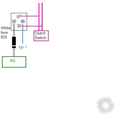
depressed ). Once you find the two wires involved with the starter interlock, follow Howard's diagram. As
mentioned, the relays' control wires ( coil ) will be the (-) Ground While Running wire ( 12 Pin connector,
White wire at Pin 10 ) from the remote starter ( Pin 85 ) and the vehicles main ignition wire ( Pin 86 ). Your
vehicle does not need a transponder bypass module, so the GWR wire is available. The 1N4004 ( or 1N4007 )
diode should be placed across relay pins 85 to 86 with the diodes band towards pin 86. ------------- Soldering is fun!
Posted By: doory100
Date Posted: February 17, 2013 at 1:50 PM
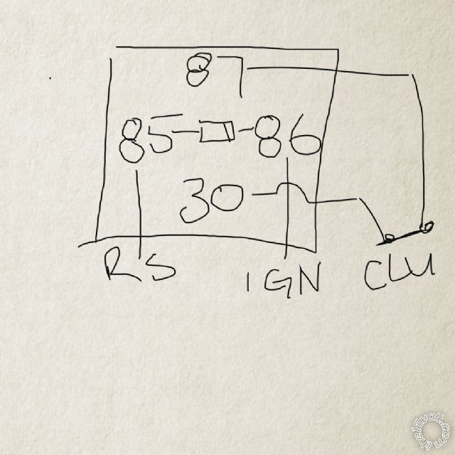
Is this correct? Diode in the middle? Or is it like howies diagram? ------------- McFly
Posted By: kreg357
Date Posted: February 17, 2013 at 2:10 PM
That will work but the extra diode on the connection between the R/S and Pin 85 in Howard's diagram won't hurt and depending on the R/S's circuit design might protect the R/S a bit. Diodes are cheap insurance.  ------------- Soldering is fun!
Posted By: doory100
Date Posted: February 17, 2013 at 4:08 PM
Perfect I have a bunch I bought anyway
-------------
McFly
Posted By: doory100
Date Posted: February 20, 2013 at 6:06 AM
Do I tap into the ignition wire from the RS or from the car itself?. Or does it matter?
-------------
McFly
Posted By: kreg357
Date Posted: February 20, 2013 at 6:20 AM
Doesn't matter. Being as the R/S Ignition1 wire is already connected to the vehicles Ignition1 wire, they are electrically the same. I generally keep the extra relays somewhat close to the R/S brain, keeps things tidy.
-------------
Soldering is fun!
Posted By: doory100
Date Posted: February 20, 2013 at 10:14 AM
Why am I placing a diode across 85 and 86 please explain it
-------------
McFly
Posted By: howie ll
Date Posted: February 20, 2013 at 10:50 AM
Solder a red wire to terminal 86 of a relay.! Solder a black wire to terminal 85 of the relay. Now hold your index finger on one terminal and your thumb on the other. Have a friend touch the other end of those wires to the respective terminals of your battery. Now have him remove and replace one of those wires. He may have to do it several times in a quick manner for you to get the full effect. The pain that you feel is the voltage spike that occurs any time an electromagnet is turned off. As you could imagine that voltage spike is not liked by a lot of the electrical equipment in your vehicle. The diode eliminates this spike. It doesn't hurt real bad. Go ahead try it. No really it doesn't. It's only 12 volts how could it shock you?
Copyright I am an Idiot.
-------------
Amateurs assume, don't test and have problems; pros test first. I am not a free install service.
Read the installation manual, do a search here or online for your vehicle wiring before posting.
Posted By: doory100
Date Posted: February 20, 2013 at 11:04 AM
I was concerned that the voltage would choose that path because of the low resistance.
-------------
McFly
Posted By: howie ll
Date Posted: February 20, 2013 at 11:11 AM
When the coil to a relay is shut down, you get an EMP in excess of 200 volts, more than enough to fry the alarm-R/S brain.
IMO it should be mandatory. You can either place it on the relay, band side to the +coil or in-line on the aux from the alarm.
Any aux from any alarm feeding relays should be so protected that's why I specify 1N4004 with a PIV of 400 volts.
Also known as an anti-spike, or quenching diode.
Sorry Kregg I couldn't resist that previous post.
-------------
Amateurs assume, don't test and have problems; pros test first. I am not a free install service.
Read the installation manual, do a search here or online for your vehicle wiring before posting.
Posted By: doory100
Date Posted: February 20, 2013 at 4:48 PM
Hey thanks guys. Starter works great!! Had a few issues due to the fact that the hood pin was not catching the hood!! Then after I got that figured out I realized that the clutch had to be bypassed. If it wasn't for the 12volt site I may never have figured this out.
-------------
McFly
Posted By: kreg357
Date Posted: February 20, 2013 at 6:15 PM
All right! Another happy Toyota. Good job!  ------------- Soldering is fun!
Posted By: bj314
Date Posted: March 30, 2013 at 9:42 AM
Hello everyone. I'm attempting my first install of a remote start alarm system. I having been trying for almost a week to get the remote starter to work on my 1995 Toyota Celica (automatic,hatchback,2.2L). I have no idea what I m doing wrong. The alarm system is a Prestige APS785. I have managed to install everything properly but the remote starter. I am unsure what to connect the yellow starter wire to. Can someone HELP please. There are 6 main wires from the ignition switch harness that must be connect to the 6pin harness on the alarm. Can you tell me exactly which ones from the brain to connect to which color wires. I have tried the way the manual says and no luck. I have even tried with and without the relay (which after 2 days I was able to figure out) but no luck. Any advice would be helpful. Thanks.
Posted By: bj314
Date Posted: March 30, 2013 at 9:47 AM
Also the manual says to put the yellow wire on the vehicle side of vehicle side of the starter cut relay. I have no idea what the starter cut relay is. I was under the impression that the starter cut relay was the same as the included starter inhibit relay since I assumed they perform the same function. Please help.
|