viper 5704v and dball
Printed From: the12volt.com
Forum Name: Vehicle Wiring Information & File Requests
Forum Discription: Request Car Alarm, Car Stereo, Cruise Control, Remote Starter, Navigation, Mobile Video, and Other Vehicle Specific Wiring Info, Manuals, Tech Tips
URL: https://www.the12volt.com/installbay/forum_posts.asp?tid=134661
Printed Date: April 05, 2026 at 2:14 AM
Topic: viper 5704v and dball
Posted By: civicjunkie
Subject: viper 5704v and dball
Date Posted: August 04, 2013 at 10:06 AM
Hi everyone. I am new to the site but i will be spending a lot of time here. A vast amount of knowledge in one place. So i searched the forums and found a couple of threads for installing an alarm in and 8th generation civic.
with that said i could not find any installs using a xpesskit dball. I was hoping someone could make an install for the 2006 -2011 civics using a viper alarm and the dball?
My set up is as follows:
2008 Honda Civic Lx sedan
Viper 5704v alarm/rs
xpesskit Dball
Also i want to use the w2w mode not the d2d mode. I have the wiring diagram from both the dball and the viper and i have matched them up to what i believe are my connections but i want to confirm i have everything done right before committing to the install.
I appreciate any help i can get with this!
Replies:
Posted By: smokeman1
Date Posted: August 04, 2013 at 3:42 PM
List what your wiring connections are so far and we can check them.
Should plan on soldering all of your connections. Have a DMM for testing all wires before making any connections. ------------- When all else fails, Read the Instructions
Support the12volt.com Make a Donation
Posted By: civicjunkie
Date Posted: August 05, 2013 at 12:15 AM
This is what i have so far.
Viper 5704v
main harness 6 pin connector
H1/1 red (+)12 volt constant - constant 12 volt
H1/2 black (-)chassis ground - ground
H1/3 brown (+)siren output - posative wire of siren
H1/4 WHITE/ brown park light isolation wire - pin 87a of onboard relay
H1/5 white parking light output - headlight switch BLACK/ white pin 11 grey
H1/6 orange (-) 500ma ground when armed outut
door lock 3 pin connector
1 blue (-) 500ma unlock output - pin 2 of 10 pin connector dball blue (-) unlock input
2 empty
3 green (-) 500ma lock output - pin 1 of 10 pin connector dball green (-) lock output
aux/shutdown/trigger harness 24 pin connector
H2/1 pink/white(-) 200ma ignition/flex relay control output
H2/2 black white (-) neutral safety input - pin 10 of 12 pin connector dball yellow/black (-) handbrake output
H2/3 blue/ white (-) 200ma 2nd status/rear defogger output
H2/4 GREEN/ black (-) 200ma oem alarm disarm output
H2/5 RED / white (-) trunk release output - pin 3 of 10 pin connector dball RED / white (-) trunk input
H2/6 green (-) door trigger input norm open norm close - pin 3 of 12 pin connector dball grren/white (-) door status output
H2/7 black yellow (-) 200ma dome light supervision output
H2/8 BROWN / black (-) 200ma horn honk output
H2/9 dark blue (-) 200ma status output - pin 10 of 10 pin connector dball blue/whote (-) GWR status input
H2/10 pink (-) 200ma ignition 1 output H2/11 white black (-) 200ma aux 3 output H2/12 violet (+) door trigger output H2/13 white violet (-) 200ma aux 1 output H2/14 violet/black (-) 200ma aux 2 output H2/15 ORANGE / black (-) 200ma aux 4 output
H2/16 brown (+) brake shutdown input - pin 6 of 12 pin connector dball grey (+) brake status output
H2/17 grey (-) hood pin input norm open norm close - pin 12 of 12 pin connector dball blue/red (-) hood status output
H2/18 violet / YELLOW (-) 200ma starter output
H2/19 blue (-) trunk pin/instant trigger input norm open norm close - pin 4 of 12 pin connector dball (-) trunk status output
H2/20 grey/black (-) diesel wait to start input - not used
H2/21 white blue (-) remote start/turbo timer activation input - not used
H2/22 orange (-) 200ma accessory output - not used
H2/23 violet white tach input - number 4 injector
H2/24 green white (-) 200ma oem arm output
remote start 10 pin heavy gauge connector
H3/1 pink (+) ignition 1 input/output H3/2 RED / white (+) fused 30a ignition 2/ flex replay input 87 H3/3 orange (+) accessory output H3/4 violet (+) starter output car side of started kill H3/5 green (+) started input key side of starter kill H3/6 red (+) fused 30a ignition 1 input H3/7 pink/white (+) ignition 2 flex relay output H4/8 pink/black (+) flex relay input 87a key side if required of flex relay H3/9 RED / black (+) fused 30a accessory/starter input H3/10 no connection
everything is in question but what is in bold i am really questioning. i want to do it myself as i have done all my audio myself and take a great deal of care to ensure everything is perfect.
Posted By: kreg357
Date Posted: August 05, 2013 at 5:03 PM
H3/1 PINK (+) IGNITION 1 INPUT/OUTPUT Blue @ Ignition Switch Harness
H3/2 RED / WHITE (87) FLEX RELAY +12V INPUT (30A FUSED) White @ Ignition Switch Harness
H3/3 ORANGE (+) ACCESSORY OUTPUT Orange @ Ignition Switch Harness
H3/4 VIOLET (+) STARTER OUTPUT (CAR SIDE) Yellow @ Ignition Switch Harness *** Cut wire
H3/5 GREEN (+) STARTER INPUT (KEY SIDE) Yellow @ Ignition Switch Harness ***Cut wire
H3/6 RED IGNITION 1 +12V INPUT (30A FUSED) White @ Ignition Switch Harness
H3/7 PINK/WHITE (30) FLEX RELAY OUTPUT Red @ Ignition Switch Harness *** Set to Accessory2 - Menu 3, Item 8, Option 2
H3/8 PINK/BLACK (87a) FLEX RELAY INPUT Not Used
H3/9 RED / BLACK ACC/STARTER RELAY +12V INPUT (30A FUSED) White @ Ignition Switch Harness
H3/10 NC No Connection
Verify that your car has a Factory Hood Pin. If it does not have one, the DB-ALL will not be able to supply the Hood Pin input to the Viper. You will then have to
install the Viper supplied Hood Pin and run a wire to that.
The clutch bypass is pretty simple. You will run the Vipers Violet / YELLOW (-) 200mA Starter Output to the correct wire at the clutch pedal interlock switch connector.
Think I have that info on file somewhere.
-------------
Soldering is fun!
Posted By: civicjunkie
Date Posted: August 05, 2013 at 10:10 PM
Awesome! Thanks kreg357!
Do i have any connections that are wrong or am i missing any connections?
Also how do i wire the trunk to open with the remote while car is running? i read somewhere i have to include a relay
Posted By: kreg357
Date Posted: August 06, 2013 at 6:11 AM
More input...
H1/5 is OK. Ensure the Viper Parking Light jumper/fuse is set to (-)
H1/6 not used
H2/1 not used
H2/3 could be used for rear defroster
H2/4 not used
H2/7 not used
H2/8 optional to Civic Horn
H2/10 not used
H2/11 not used
H2/12 not used
H2/13 not used
H2/14 not used
H2/15 not used
H2/18 for clutch interlock bypass - ref PM
H2/23 Tach to DB-ALL Violet/White Tach Output
H2/24 not used
Does your Civic have a trunk release button on the Factory FOB? For the Viper to control a trunk release thru the DB-ALL, the Civic must have the trunk release solenoid. Some
Civic's only had a release lever and cable going to the trunk...
-------------
Soldering is fun!
Posted By: civicjunkie
Date Posted: August 07, 2013 at 5:32 PM
Kreg357
H2/3 I would like to use this for the defroster but know how. Read something somewhere about the light coming on/not coming on the dash. Where/how would wire this up?
H2/23 My understanding is i have to wire this direct whether D-BALL is D2D or W2W is this correct? Also do you mean run wire from the tach to the DB-ALL Violet/White Tach Output?
Yes my factory fob as the trunk button.
I am sure i will have more questions as i go. Is it ok if i refer the questions back here to you?
Posted By: civicjunkie
Date Posted: August 07, 2013 at 6:22 PM
i am still confused with this:
- H1/4 WHITE/ brown park light isolation wire - pin 87a of onboard relay
- H2/6 green (-) door trigger input norm open norm close - pin 3 of 12 pin connector D-BALL GREEN / WHITE (-) door status output [do i have to set this for normally open or normally close or does it auto detect? some confusion with this wire]
- H2/17 grey (-) hood pin input norm open norm close - pin 12 of 12 pin connector D-BALL blue/red (-) hood status output [again not sure what to do with the norm open or norm close]
- H2/19 blue (-) trunk pin/instant trigger input norm open norm close - pin 4 of 12 pin connector D-BAL (-) trunk status output [ im starting to think that the norm open norm close means these wires r a status indicator but please inform me if i am worng! ]
- H3/4 violet (+) starter output (car side) yellow @ ignition switch
- H3/5 green (+) starter input (key side) yellow @ ignition switch harness ***cut wire
[Do i wire these to together at the yellow on the ignition harness? what do you mean by cut wire? ]
there are a few different wires going to the white wire on the ignition harness as well. they all get wired to the same white wire?
Posted By: kreg357
Date Posted: August 07, 2013 at 7:46 PM
H2/3 I would like to use this for the defroster but know how. Read something somewhere about the light coming on/not
coming on the dash. Where/how would wire this up?
Here is the info from AudioVox : Rear Defrost BROWN (-) @ A/C CONTROL PANEL
You will have to test for this wire and once found, determine if it needs a single trigger pulse or a Latched output. I
believe it needs a Latched, so you will set the H2/3 Blue/White wire for the 10 minute latched output ( Menu 3, Item 11, Option 2 ).
Most likely the Civic's Rear Defrost light will not come on, but the defroster grid will.
H2/23 My understanding is i have to wire this direct whether D-BALL is D2D or W2W is this correct? Also do you mean
run wire from the tach to the DB-ALL Violet/White Tach Output?
My assumption was you were going W2W from the other wire connections. If you are going D2D, it depends on the R/S
whether if can obtain the Tach signal via the D2D harness. Just wire it directly between the R/S Tach Input and the
DB-ALL Tach Output and all will be OK.
Yes my factory fob as the trunk button.
Then you should be OK with connecting the R/S's Trunk Release Output to the DB-ALL's Trunk Release Input.
- H1/4 WHITE/ brown park light isolation wire - pin 87a of onboard relay
On some vehicles ( think I remember a 2006 Impala ) require this type connection to prevent damage to the BCM. It can be
used in some Chrylser vehicles with the light MUX wire and a resistor to get the Parking Lights on. Your Civic is very
simple and only needs a (-) applied to the Parking Light wire.
- H2/6 green (-) door trigger input norm open norm close - pin 3 of 12 pin connector D-BALL GREEN / WHITE (-) door status output
[do i have to set this for normally open or normally close or does it auto detect? some confusion with this wire]
The Default setting ( NO ) is correct for your Civic and the DB-ALL's output.
- H2/17 grey (-) hood pin input norm open norm close - pin 12 of 12 pin connector D-BALL blue/red (-) hood status output
[again not sure what to do with the norm open or norm close]
Same answer, your Civic is NO style ( as is the DB-ALL's output ). Here is Vipers description :
1-9 Hood Trigger (Normally Open): Hood trigger (normally closed). To program
the unit for either a normally open (rests open, or at 12v when the hood
is closed) or a normally closed (rests at ground when the hood is closed) pin
switch.
- H2/19 blue (-) trunk pin/instant trigger input norm open norm close - pin 4 of 12 pin connector D-BAL (-) trunk status output
[ im starting to think that the norm open norm close means these wires r a status indicator but please inform me if i am worng! ]
Correct, same.
- H3/4 violet (+) starter output (car side) yellow @ ignition switch
- H3/5 green (+) starter input (key side) yellow @ ignition switch harness ***cut wire
[Do i wire these to together at the yellow on the ignition harness? what do you mean by cut wire? ]
The Starter Kill circuit is actually a relay built into the Viper brain. The purpose is to prevent the car from starting by
interrupting the cars ignition switch starter wire when the Viper is armed / locked. To incorporate this feature, you must
cut the Civic Yellow Starter wire ( in a convenient / accessible ) place and make very solid / reliable ( solder ) connections
to the Violet and Green Viper wires, as indicate to the correct sides of the cut Yellow wire.
This Starter Kill circuit is not mandatory. If you don't want this feature or don't want to cut the Civic's starter wire, then
just connect the Vipers Violet wire to the un-cut Civic Yellow starter wire ( leave the H3/5 Green wire not connected ).
there are a few different wires going to the white wire on the ignition harness as well. they all get wired to the same white
wire?
Yes. Your Viper has 4 power wires that need to be connected to a +12V constant source of sufficient current rating. As long
as it's just the Viper with the basic siren and connected to the (-) Parking Lights, you will be fine using the White wire at
the ignition harness. It has a 50 Amp rating. With the Civic install, do not combine all the Viper power wires into one wire
and run that one wire to the Civic's White wire.
-------------
Soldering is fun!
Posted By: civicjunkie
Date Posted: August 07, 2013 at 10:07 PM
Here is the info from AudioVox : Rear Defrost BROWN (-) @ A/C CONTROL PANEL
You will have to test for this wire and once found, determine if it needs a single trigger pulse or a Latched output. I
believe it needs a Latched, so you will set the H2/3 Blue/White wire for the 10 minute latched output ( Menu 3, Item 11, Option 2 ).
Most likely the Civic's Rear Defrost light will not come on, but the defroster grid will.
How will i test that wire? If its a pulse i will get a pule at that wire and if its latched i will get a constant?
Yes. Your Viper has 4 power wires that need to be connected to a +12V constant source of sufficient current rating. As long
as it's just the Viper with the basic siren and connected to the (-) Parking Lights, you will be fine using the White wire at
the ignition harness. It has a 50 Amp rating. With the Civic install, do not combine all the Viper power wires into one wire
and run that one wire to the Civic's White wire.
Do not combine the wires because the one single wire will not be able to supply the amps right? I have a proximity sensor as well. Should i run a decent gauge wire in to supply the 12v constant?
Posted By: kreg357
Date Posted: August 07, 2013 at 10:23 PM
The Brown Defrost wire is listed as (-). Set you DMM to 20V DC, connect the Red test lead to +12V constant and the Black
test lead to the Brown suspect wire. Start the engine and turn on the defroster. The DMM will either pulse a brief +12V
or the DMM will show a constant +12V. Set the Viper accordingly. Pretty sure it will be a constant / latched signal.
Do not combine the wires because the one single wire will not be able to supply the amps right?
Correct. Each Viper H3 power wire is rated at 30 Amps.
Don't think the prox sensor will be drawing a whole lot of amps, especially when the engine is remote started. You should
be OK running everything to the White wire. Finding space for four separate solder connections along a few inches of the
White wire shouldn't be an issue. Running a large gauge fused wire from the battery thru the firewall and making the Viper's
connections inside the Civic is another possibility.
-------------
Soldering is fun!
Posted By: civicjunkie
Date Posted: August 09, 2013 at 7:24 PM
one more stupid question:
the wiring harness for the two items D-BALL and Viper are 4000 feet long. Can i cut them and shorten them to bring the two closer together or will it affect anything due to Independence changes in the wires??
Posted By: kreg357
Date Posted: August 10, 2013 at 4:28 AM
Yep, cut to length. There will be no issues with impedance due to wire length. Best practice is to "bench prep" the two modules by mating them on the bench, under ideal conditions, prior to install. As shown below, cut to length, solder & heat shrink all the necessary inter-connections. Then neaten and secure the wires. The wires that go to the vehicle can be neatly bundled in groups according to their final destination.
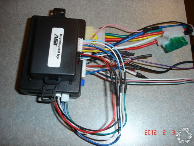 ------------- Soldering is fun!
Posted By: civicjunkie
Date Posted: August 13, 2013 at 8:43 PM
I have all my bench wiring done. I am confused with the shock sensor. The wire harness for it will fit in the viper or the D-BALL. I am assuming it goes into the viper but i want to be sure. Also the green wire on the harness is looped back on itself at one end and the other end is not attached to anything. The back of the shock sensor indicates the green wire is warn (-) output. So my question is what do i do with the unattached end of the green wire and which end of the harness (the looped, or single green wire end) do i attach to the viper and which to the D-BALL?
Posted By: civicjunkie
Date Posted: September 26, 2013 at 10:48 AM
can anyone help me wrap this up??
1) instructions say to use 7 pin immobilizer connector pin 3 lt grn immo data and pin 4 pink sw can. Problem is pin 4 is not pink its like a beige color. im not trying to be fussy but there is another wire in that connector that is clearly pink. what do i do
also reading on here i read that connector is suppose to be lime green but its white in my car. do i have the wrong connector
2) instructions say to use 18 pin plug above driver kick pin 16 grn lock and pin 12 gray unlock but reading on here it says to use pin 27 and 28 of 34 pin connector. which is better to use?
trying to get this done today please help
Posted By: kreg357
Date Posted: September 26, 2013 at 7:46 PM
Here is more info from iDatalink & Fortin on the 2008 Civic transponder plug :
Ignition White 7 pin plug Pin 2 Yellow (+)
Key Data White 7 pin plug Pin 3 Light Green (DATA)
SWC White 7 pin plug Pin 4 Pink (DATA)
Look for that color sequence on the 7 Pin transponder connector. The wire at Pin 4 can look slightly
Orange to Beige. ( The one in the Civic Pictorial looks somewhat Orange.) Either way use the wire at
Pin 4.
The lock wires are the same at either location so use whichever one is easiest for you to make your
connections. The 34 Pin plug is found at the backside of the fuse box ( side towards the engine ).
-------------
Soldering is fun!
Posted By: civicjunkie
Date Posted: September 26, 2013 at 8:54 PM
Thank you kreg357! you are a life saver! now the yellow ignition wire in pin 2 of the 7 pin plug is not the yellow ignition wire that i am cutting for the ignition output and input right?? that yellow wire i will be cutting and using will be from the connector with the larger gauge wire right??
Posted By: kreg357
Date Posted: September 26, 2013 at 9:22 PM
Correct. This small yellow wire is an Ignition wire, not a Starter wire. Use the thick Yellow Starter wire on the main ignition connector / harness for your H3/4 and H3/5 connections.
-------------
Soldering is fun!
Posted By: civicjunkie
Date Posted: October 17, 2013 at 5:36 PM
kreg357 wrote:
Correct. This small yellow wire is an Ignition wire, not a Starter wire. Use the thick Yellow Starter wire on the main ignition connector / harness for your H3/4 and H3/5 connections.
Kreg357 i hope you are still around. Everything works with the viper but the remote start! When i try to remote start the park lights flash 7 times. The install guide Says "7 flashes - manual transmission mode is enabled and not initialized"
Also when i perform the shutdown diagnostics i also get 7 flashes from the control center it says "7 flashes - Timer mode/Turbo mode/Manual mode error"
What am i doing wrong??
Posted By: civicjunkie
Date Posted: October 17, 2013 at 6:14 PM
nevermind did some digging around and got it figured out. read that i would have to initialize it every time so put it in auto mode Thanks so much for your help
one question, i have my parking lights hooked up to the switch at the steering column. when i use the viper fob i notice it causes the light on the dash to illuminate for a brief moment indicating the lights are on. I seen somewhere that a remote start was installed (in the same car as mine)and a red wire down near the driver kick was used for parking lights. if i used this instead would it still cause the indicator on the dash to come on still??
Posted By: kreg357
Date Posted: October 18, 2013 at 2:58 PM
Re: Parking Lights
Never tried the (+) Parking Light wire. I always go for the (-) wire when available. The fact that the instrument panel illuminates should be considered normal as that is what happens when you turn on the Parking Lights.
-------------
Soldering is fun!
|