2011 toyota tundra rheostat wiring
Printed From: the12volt.com
Forum Name: Vehicle Wiring Information & File Requests
Forum Discription: Request Car Alarm, Car Stereo, Cruise Control, Remote Starter, Navigation, Mobile Video, and Other Vehicle Specific Wiring Info, Manuals, Tech Tips
URL: https://www.the12volt.com/installbay/forum_posts.asp?tid=135444
Printed Date: May 12, 2026 at 3:07 PM
Topic: 2011 toyota tundra rheostat wiring
Posted By: jmsingh
Subject: 2011 toyota tundra rheostat wiring
Date Posted: December 03, 2013 at 2:49 PM
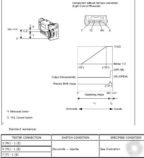
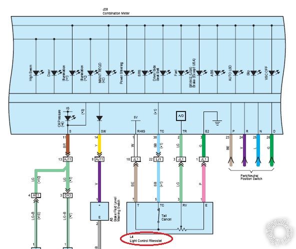
Hello; I am trying to tap/splice into the rheostat dimmer switch that controls the dash lighting. I have added some LEDs and wish to control these via the rheostat such that they function relative to all other dash/panel controlled lighting. I have the following EWD from TIS, but am not sure which wire to connect to (ie: T, TC, or RV).
Thanks in advance.
Replies:
Posted By: oldspark
Date Posted: December 03, 2013 at 4:34 PM
You need to substitute a later PWM dimmer. Rheostat types will not dim LEDs in proportion to position or tungsten bulbs.
Posted By: jmsingh
Date Posted: December 03, 2013 at 7:36 PM
oldspark wrote:
You need to substitute a later PWM dimmer. Rheostat types will not dim LEDs in proportion to position or tungsten bulbs.
Thanks for the reply. Please excuse my ignorance, but could you help me understand what you mean? The stock rheostat/dimmer dial in the dash is currently used to adjust the lighting levels for the dash and these are LEDs.
Am not challenging you on the response, I just don't understand.
Posted By: oldspark
Date Posted: December 03, 2013 at 8:56 PM
Challenging - as in rude etc? No way! Seeking clarification or extra proof/support IMO is a positive thing.
What is challenging however is for ME to provide a good answer! (LOL)
My other challenge is to read OPs or replies correctly. In you case I totally missed that the existing dimmer is dimming LEDs, hence it must be a PWM type as opposed to a "rheostat" type assuming the LEDs dim similarly to any also-connected tungsten lamps, or in proportion to dial position.
There are other methods that are not PWM based, but they are relatively complex, and PWM dimmers have been "standard" in vehicles for many years.
I'd suggest you connect your added LEDs across the existing dimmed LEDs/bulbs but with the -ve end doing to whatever you are using to switch them on. That assumes the dimmer/PWM can power the extra LEDs. If not, you may fry whatever switching device is involved (probably a MOSFET) and may have to add a buffer to prevent that (ie, another MOSFET etc).
From what I see, all your dash etc LEDs have their +V supplied from the dimmer else fixed +V source, and the rheostat is merely that - and external potentiometer that interfaces to TR - ie, the A/D = analog to digital converter, hence PWM = dimmer.
Connecting to the rheostat itself will not achieve what you want.
Note that I originally thought the "rheostat" was the entire modular dimmer circuit as fitted to many vehicles (typically 3 terminals: +12V, GND, and output to bulbs/LEDs - typically their /GND side).
Posted By: jmsingh
Date Posted: December 03, 2013 at 9:30 PM
I may have bitten off more than I can chew here. At least now I know what A/D means on the diagram, but what about TR? No, really!
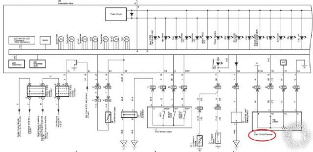
I'm adding the panel below. The text has back-lighting and the instructions simply say to connect the black to ground and the red to the dimmer circuit.

If I understand correctly, connecting the the PWN will not achieve the desired result? I should connect to one of the existing LEDs on the dash?
Posted By: Ween
Date Posted: December 03, 2013 at 9:45 PM
with a meter you should be able to determine the positive and negative leads at a dash illumination LED. connect accordingly.
mark
Posted By: oldspark
Date Posted: December 03, 2013 at 9:49 PM
TR? Maybe trim resistor?
Your LED- to GND and LED+ to the dimmer/PWM is consistent with how I interpret your wiring diagrams.
But no - or yes - connecting to the PWM will achieve the desired result, but that rheostat and TR output is not (the) PWM.
You need to connect to the PWM output which I presume is one of the 2 lines from the upper-left box (Power S...???) in your middle diagram; and I'd assume it's the upper output (since the upper powers the lower thru the diode if the lower output of off, and you don't want +12V supplying the PWM output when it is off).
Posted By: jmsingh
Date Posted: December 04, 2013 at 8:56 AM
Think I have it now.
Thanks for the replies and information.
|