2005 nissan pathfinder viper 5704
Printed From: the12volt.comForum Name: Vehicle Wiring Information & File Requests
Forum Discription: Request Car Alarm, Car Stereo, Cruise Control, Remote Starter, Navigation, Mobile Video, and Other Vehicle Specific Wiring Info, Manuals, Tech Tips
URL: https://www.the12volt.com/installbay/forum_posts.asp?tid=135575
Printed Date: May 11, 2026 at 9:15 PM
Topic: 2005 nissan pathfinder viper 5704
Posted By: aharrison999
Subject: 2005 nissan pathfinder viper 5704
Date Posted: December 19, 2013 at 11:08 PM
Replies:
Posted By: kreg357
Date Posted: December 20, 2013 at 6:45 AM
Wow, I could write a book on this one. OK, I will try to cover the major areas.
First, the Viper 5704. Nice system, good choice. That's the good news. The not so good news.
Viper is manufactured by DEI. DEI categorizes Viper as a brand for their authorized, professionally trained 12V dealers.
They will not support DIYers and will not honor a warranty on a DIY installed system. Additionally they restrict full install
guides to their authorized dealers, so there will be only a brief 2 page guide in the 5704's box. However, you should be able
to get a 570x install guide in the Downloads section.
Viper 5704 is a full featured, very robust system. The 5704 install guide does not go into great detail about wire function
and programming features. The older 5701 guides are slightly better in this respect. Either way, the DEI documents are
not written for the DIYer, they are written for DEI trained dealers, using industry and manufacturer specific terms. Additionally
there are several vague areas and "gotcha's" with the 570x units that almost all DIYers fall victim to. This info has been
asked and answered many times on this forum and easily found with a search. ( Transmission Mode, Neutral Safety Switch
and Engine Checking Mode )
Second, the bypass module. This is another area where this is a lot to know and learn. It is another area where the
bypass module manufactures cater to the 12V professional and will shun the DIYer. The XpressKit XK02 is a nice module
but it will only handle the "Convenience" features on your Pathfinder, IF it is flashed with the NISSDL V3.02 firmware. The
XK02 bypass module can be flashed with many different firmwares that allow it to support a wide variety or vehicles. If
your XK02 has a white label on it that is marked NISSDL, then that is the firmware that was flashed on it at the factory and
you are all set. If not, hopefully the seller re-flashed it to the correct NISSDL firmware for you ( or you have the XKLoader2
cable to flash it yourself ). Either way this module will not perform the ignition immobilizer transponder bypass function
needed for the remote start to work. It only handles the door locks and alarm. If your Pathfinder has a chipped transponder
key, you will need another bypass module to handle this. If you haven't already purchased the XK02, I would suggest a DLPK,
for several reasons. The DLPK will do everything the XK02 w/NISSDL will do plus the transponder bypass plus supply door,
hatch and hood status signals and it comes pre-loaded and ready to go right out of the box. Here is a link to the DLPK's install
guide : https://www.xpresskit.com/DocumentDownload.aspx?documentid=5665&productid=122&firmwareid=1632
Bottom line - there is a big learning curve involved. You have chosen to do a self install, you will be testing and locating
the correct wires in the Pathfinder to make the necessary connections. You will be soldering the wires, programming
the Viper and bypass module. Most importantly, you or your family members will be driving this vehicle for years to come.
If you are up to the challenge, here is a list of sources for the wiring in your vehicle :
Here is a link to Bulldog Security : https://www.bulldogsecurity.com/bdnew/vehiclewiringdiagrams.asp
Here is a link to Ready Remote : https://www.readyremote.com/main.asp
Here is a link to AudioVox : https://techservices.audiovox.com/AccessRequest.aspx Sign-up & info is free.
Download all available sources and compile it into a working list for your install.
Here is a link to the 5704 install guide : https://www.the12volt.com/installbay/file.asp?ID=1204
Here is a link to an older, but more detailed 5701 install guide : https://www.the12volt.com/installbay/file.asp?ID=710
Please note that the wiring connectors have been changed but the wire names / descriptions ( and usually colors ) remain the
same. Read, learn and understand the system. Ask questions on the vague areas.
Finally, make up with a list of Viper to Pathfinder or bypass and bypass to Pathfinder. Post that for member review and
advice. Here is a 5704 harness list to save you some typing...
Viper 5704
H1/1 RED (+)12VDC CONSTANT INPUT
H1/2 BLACK (-) CHASSIS GROUND
H1/3 BROWN (+) SIREN 0UTPUT
H1/4 WHITE/ BROWN PARKING LIGHT 87A
H1/5 WHITE PARKING LIGHT OUTPUT
H1/6 ORANGE (-) 500mA GR0UND WHEN ARMED 0UTPUT
H2/1 PINK/WHITE (-) 200mA IGNITION/FLEX RELAY
H2/2 BLACK/ WHITE (-) NEUTRAL SAFETY INPUT
H2/3 BLUE/WHITE (-) 200mA 2ND STATUS /REAR DEFOG
H2/4 GREEN/ BLACK (-) 200mA OEM ALARM DISARM
H2/5 RED / WHITE (-) 200mA TRUNK RELEASE OUTPUT
H2/6 GREEN (-) D00R TRIGGER INPUT (N/C 0R N/0)
H2/7 BLACK / YELLOW (-) 200mA DOME LIGHT SUPER
H2/8 BROWN / BLACK (-) 200mA HORN HONK OUTPUT
H2/9 DARK BLUE (-) 200mA STATUS OUTPUT
H2/10 PINK (-) 200mA IGNITI0N 1 OUTPUT
H2/11 WHITE/ BLACK (-) 200mA AUX 3 OUTPUT
H2/12 VIOLET (+) D00R TRIGGER INPUT
H2/13 WHITE/ VlOLET (-) 200mA AUX 1 OUTPUT
H2/14 VIOLET/BLACK (-) 200mA AUX 2 OUTPUT
H2/15 ORANGE / BLACK (-) 200mA AUX 4 OUTPUT
H2/16 BROWN (+) BRAKE SHUTD0WN INPUT
H2/17 GREY (-) H00D PIN INPUT (N/C 0R N/0)
H2/18 VIOLET / YELLOW (-) 200mA STARTER OUTPUT
H2/19 BLUE (-) TRUNK PIN / INSTANT TRIGGER INPUT (N/O)
H2/20 GREY/BLACK (-) DIESEL WAIT T0 START INPUT
H2/21 WHITE'/BLUE (-) REMOTE START/ TURBO TIMER INPUT
H2/22 ORANGE (-) 200mA ACCESSORY OUTPUT
H2/23 VIOLET/WHITE TACHOMETER INPUT
H2/24 GREEN / WHITE (-) 200mA OEM ALARM ARM OUTPUT
1 PINK (+) IGNITION 1 INPUT/OUTPUT
2 RED / WHITE (30A) FUSED IGNITION 2
3 ORANGE ACCESSORY OUTPUT
4 VIOLET (+) STARTER OUTPUT (CAR SIDE)
5 GREEN (+) STARTER INPUT (KEY SIDE)
6 RED (+) FUSED (30A) IGNITION 1 INPUT
7 PINK/WHITE (+) IGNITION 2 / FLEX RELAY
8 PINK/BLACK FLEX RELAY INPUT 87A
9 RED / BLACK FUSED (30A) ACC/STARTER INPUT
Door Lock
1 Blue (-) 500 mA Unlock
2 Green (-) 500mA Lock
-------------
Soldering is fun!
Posted By: aharrison999
Date Posted: December 20, 2013 at 11:07 AM
I was very misdirected from the company I purchased the XK02 from. They informed me it would work as an immobilizer. I just ordered the DLPK you recommended and should have it by Monday. I will start going over the reference material you provided and I'm sure I will have questions!
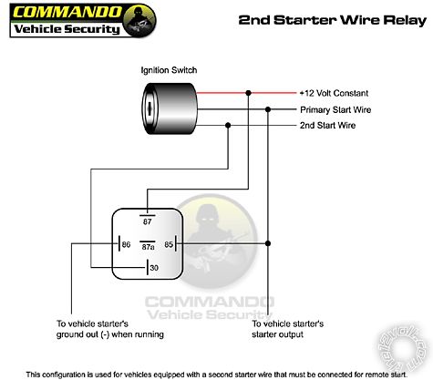
One question I know of right now... my vehicle has a 2nd starter wire. I have seen several recommended ways of wiring this with a relay... some with a diode, some without, how do you recommend I wire the 2nd starter wire in my application?
Thanks Again!
Posted By: kreg357
Date Posted: December 20, 2013 at 12:05 PM
Personally, I would use the Viper 5704's Pink/White Flex relay output for the all important Starter2 wire and use an external SPDT 30/40 Amp relay for Pathfinders' Accessory2 wire. That way all ignition circuits are powered via an isolated circuit during a remote start. The Viper 5704 makes this fairly easy with it's (-) 200mA Accessory output.
-------------
Soldering is fun!
Posted By: aharrison999
Date Posted: December 20, 2013 at 1:30 PM
Posted By: kreg357
Date Posted: December 20, 2013 at 3:11 PM
Yes that method will work, however, as mentioned previously, the Viper has low current (-) outputs for this exact situation.
OK, if you don't want to use the Vipers Flex relay for the Pathfinders Starter2 output, here is the way I would do it with the Viper.
1 PINK (+) IGNITION 1 INPUT/OUTPUT Pathfinder IGN1
2 RED / WHITE (30A) FUSED FLEX RELAY INPUT +12V Constant
3 ORANGE ACCESSORY OUTPUT Pathfinder ACC1
4 VIOLET (+) STARTER OUTPUT (CAR SIDE) Pathfinder Starter1
5 GREEN (+) STARTER INPUT (KEY SIDE) Pathfinder Starter1
6 RED (+) FUSED (30A) IGNITION 1 INPUT +12V Constant
7 PINK/WHITE (+) IGNITION 2 / FLEX RELAY OUTPUT Pathfinder ACC2 ***Program Menu 3, Item 8 to Option 2
8 PINK/BLACK FLEX RELAY INPUT 87A of FLEX RELAY Not Used
9 RED / BLACK FUSED (30A) ACC/STARTER INPUT +12V Constant
10 N/C N/C
Extra SPDT Relay for Starter2 :
Relay Pin 85 to Viper Violet (-) 200mA Starter Output
Relay Pins 86 and 87 to +12V constant thru 20 Amp fuse
Relay Pin 30 to Pathfinder Starter2
Relay Pin 87a not used - insulate
-------------
Soldering is fun!
Posted By: aharrison999
Date Posted: December 20, 2013 at 9:52 PM
Are you suggesting that I use the Pathfinder's ACCESSORY /HEATER BLOWER2(GREEN/ YELLOW) wire as a power source for the Starter2 wire through an external relay triggered by the Viper's (-) 200mA Accessory output?
Pathfinder ACCESSORY /HEATER Blower2 to Relay 87
Pathfinder Starter2 to Relay 30
Relay 86 to ground
Relay 85 to Viper (-) 200mA Accessory output
Correct??? Any diodes or extra fuses anywhere?
Posted By: kreg357
Date Posted: December 21, 2013 at 5:18 AM
R/S source to duplicate a normal key start-up. The Viper can directly support only 4 of those 5 ignition wires. The Viper has one
Ignition, one Starter and one Accessory output on the H3 harness. The Viper also has a Flex Relay output, H3/7. The Factory Default
setting for this wire is Ignition2. This setting can be changed via Viper Menu 3 programming to either Accessory or Starter type
output, depending on the vehicles needs.
Your vehicle does not need an Ignition2 connection. It does need a Starter2 and an Accessory2 connection. Being as the Starter2
ignition wire is more important, I chose to use the Flex Relay ( H3/7 Pink/White wire ) for the Pathfinders Starter2 circuit. That would
leave the Accessory2 circuit to an external relay. You have shown a desire to power the Starter2 circuit with an external relay. While
that wasn't my first choice, it is an acceptable way to accomplish the install. My 12/20/2013 post at 4:11 PM shows the exact wiring and
programming to do this.
The relay wiring you posted for Starter2 from Commando Alarms will work but does have one slight concern. Both this extra relay
and the DLPK bypass module need a (-) Ground When Running signal. Fortunately, the Viper 5704 does have two of these outputs. Use
the Dark Blue (-) 200mA Status Output for the DLPK and the BLUE/WHITE (-) 200mA 2ND STATUS /REAR DEF0GGER OUTPUT for the
Starter2 relay Pin 86 input. And if you read up in the Relay Section, you will see that standard relay protocol has Pin 85 as the (-)
and Pin 86 as the (+) coil inputs which Commando Alarms did not follow. My relay wiring avoided this issue by using the Vipers low
current (-) output to control the external relay.
Anyway, going with your desire to power the Pathfinders Starter2 circuit with an external relay, I provided the H3 and relay wiring
for this configuration. Using an external relay for Starter2 means that the Vipers Flex relay can be used for the Pathfinders
Accessory2 wire and is shown in that previous post. The Starter2 external Relay wiring is shown using the Vipers low current 200mA
(-) Starter Output, not the way the Commando Alarms diagram did it ( although that will also work ). As shown above the external
Starter2 relay gets its' +12V power on Pin 86 and 87 from the Pathfinder. The Green wire at the Pathfinders ignition switch connector is
rated at 40 Amps and, in normal use, is capable of supplying all of the vehicles ignition switch wires and can be used as the relays
+12V constant power source.
My original "preferred" way, using the Vipers Flex Relay for the Starter2 circuit and the external relay for the Accessory2 circuit
would look like this :
1 PINK (+) IGNITION 1 INPUT/OUTPUT Pathfinder IGN1
2 RED / WHITE (30A) FUSED FLEX RELAY INPUT +12V Constant
3 ORANGE ACCESSORY OUTPUT Pathfinder ACC1
4 VIOLET (+) STARTER OUTPUT (CAR SIDE) Pathfinder Starter1
5 GREEN (+) STARTER INPUT (KEY SIDE) Pathfinder Starter1
6 RED (+) FUSED (30A) IGNITION 1 INPUT +12V Constant
7 PINK/WHITE (+) IGNITION 2 / FLEX RELAY OUTPUT Pathfinder Starter2 ***Program Menu 3, Item 8 to Option 3
8 PINK/BLACK FLEX RELAY INPUT 87A of FLEX RELAY Not Used
9 RED / BLACK FUSED (30A) ACC/STARTER INPUT +12V Constant
10 N/C N/C
Extra SPDT Relay for Accessory2 :
Relay Pin 85 to Viper Orange (-) 200mA Accessory Output
Relay Pins 86 and 87 to +12V constant thru 20 Amp fuse
Relay Pin 30 to Pathfinder Accessory2
Relay Pin 87a not used - insulate
Either way posted will work and power all the necessary ignition wires in the Pathfinder. The choice is yours, you can even substitute
the Commando Alarm Starter2 relay wiring ( and even use my suggestion for the GWR input ). Every installer will do the wiring
slightly differently. It's all personal preference, usually derived from experience.
-------------
Soldering is fun!
Posted By: aharrison999
Date Posted: December 23, 2013 at 8:40 AM
Thanks for all your help!
Posted By: kreg357
Date Posted: December 23, 2013 at 7:33 PM
Personally, I'm old school. I still do most installs in the W2W mode. But I do enjoy soldering. 
It takes longer and requires some heat shrink tube, solder, tie wraps and electric tape but it always works and you know exactly which wire does what.
With the components you have chosen, you should be able to go D2D 2-way pretty easily and it should work. It will save you about seven wires.
The choice is yours. You can try D2D 2-way and if that doesn't work, you can always switch over to W2W, as long as
you don't cut short or de-pin your unused wires.
The next area of concern is :
1. Does your Pathfinder have the Factory Alarm system?
2. Does your Pathfinder have a Factory Hood Trigger?
The answer to question 1 will determine if you have to run wires to empty pin holes in a BCM connector.
The answer to question 2 will determine if the DLPK will supply the Hood Status or if you must install the Viper kit's
hood pin.
-------------
Soldering is fun!
Posted By: aharrison999
Date Posted: December 23, 2013 at 8:25 PM
It does have factory alarm, does that mean I have to hardwire to arm/disarm the factory alarm or will the d2d handle that?
I don't see a factory hood pin... Guess that means I need to install one... or can I just ground the hood pin wire?
Posted By: kreg357
Date Posted: December 23, 2013 at 9:14 PM
Factory Alarm is additional labor. Check your BCM 40 Pin Plug for these wires
Lock/Arm BCM White 40 pin 08 LtBlue (-) BCM right of steering column
Unlock/Disarm BCM White 40 pin 07 Gray (-) BCM right of steering column
Here is a photo of a BCM ( 2011 Rogue ) :
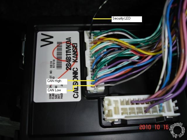
If the wires are not there and the pins are empty you will need a few 1N400x diodes. RadioShack usually has them. You can get
1N4001, 1N4004 or 1N4007 diodes. You will be inserting a diode leg into the BCM empty pin holes for Lock and Unlock. The
diodes leg diameter is the correct size to make solid contact with the BCM connector inside. Solder the R/S's Lock and Unlock
wire outputs to the diodes other leg, diode stripe towards the R/S. Use heat shrink tube to insulate this wire / diode assy and
secure it to the other wires in the BCM's harness with tie wraps or electrical tape to prevent it from being pulled out. The DLPK
install guide has a diagram of the BCM connector and the empty pin locations.
The photo above also shows the CAN wires. You can get the CAN wires at the OBD2 connector, too.
CanHi OBD2 White 16 pin 06 Blue (DATA)
CanLo OBD2 White 16 pin 14 Pink (DATA)
Test for the Factory Hood Pin by sitting in the Pathfinder and setting it's alarm. Wait a few minutes and pull the hood release.
If the horn starts beeping, the hood is monitored and the DLPK will provide a Hood Trigger signal. If it does not set off the alarm,
you can add the hood pin supplied in the kit. It is used for both the Viper Alarm system and the Viper remote start system.
It will prevent a remote start if the hood is open ( like during engine service ) and will shutdown a remote started engine if the
hood is opened. If you don't want to drill a hole in your Pathfinder, you can either fabricate a mounting bracket that uses
existing bolts or use a mercury tilt switch mounted as shown below :
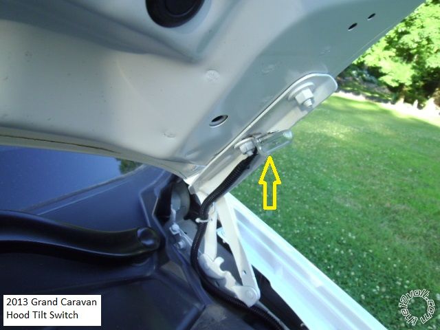
Please note that a mercury tilt switch, when adjusted properly, will not trigger until the hood is raised at least half way open.
-------------
Soldering is fun!
Posted By: magnamagus
Date Posted: February 06, 2014 at 2:41 AM
When making connections to the BCM Lock and unlock, you stated that the Diode Stripe side (-) should be pointed toward the remote start, and the Positive side is connected to the BCM.
1. Does this protect the BCM by preventing positive current going into the BCM?
2. Are the Lock and Unlock wires necessary if these are handled by the BYPASS MODULE?
-------------
Erick
Posted By: bknudsen89
Date Posted: October 23, 2014 at 2:39 PM
I am also doing my first ever rs install of the viper 4104 w/ dball2. I was looking over this post and first of all thank you so much for all of your knowledge. I am a little confused though as to what I need to do with all of those 30A fuse lines that are connected to 12V constant ( those not being connected to a relay). For my car at the ignition switch it shows the 12V Constant wire as green. Do all of these connections divide into this one wire? Or how do you propose these are connected? Using diodes? Sorry if I'm a bit confusing all help would be appreciated.
Posted By: howie ll
Date Posted: October 23, 2014 at 5:11 PM
For most manufacturers it's white, WHITE/ red, and red plus one or two e.g.Toyota, black
-------------
Amateurs assume, don't test and have problems; pros test first. I am not a free install service.
Read the installation manual, do a search here or online for your vehicle wiring before posting.
Posted By: bknudsen89
Date Posted: October 23, 2014 at 5:41 PM
Posted By: howie ll
Date Posted: October 23, 2014 at 5:44 PM
-------------
Amateurs assume, don't test and have problems; pros test first. I am not a free install service.
Read the installation manual, do a search here or online for your vehicle wiring before posting.
Posted By: howie ll
Date Posted: October 23, 2014 at 5:46 PM
Oops,just checked you're quite correct its green.
-------------
Amateurs assume, don't test and have problems; pros test first. I am not a free install service.
Read the installation manual, do a search here or online for your vehicle wiring before posting.
Posted By: bknudsen89
Date Posted: October 23, 2014 at 5:56 PM
Posted By: bknudsen89
Date Posted: October 23, 2014 at 6:42 PM