2014 Chevrolet Spark Alarm and Stereo Wiring
Printed From: the12volt.com
Forum Name: Vehicle Wiring Information & File Requests
Forum Discription: Request Car Alarm, Car Stereo, Cruise Control, Remote Starter, Navigation, Mobile Video, and Other Vehicle Specific Wiring Info, Manuals, Tech Tips
URL: https://www.the12volt.com/installbay/forum_posts.asp?tid=136382
Printed Date: April 12, 2026 at 1:04 PM
Topic: 2014 Chevrolet Spark Alarm and Stereo Wiring
Posted By: decibel jj
Subject: 2014 Chevrolet Spark Alarm and Stereo Wiring
Date Posted: April 02, 2014 at 1:55 PM
Does anyone have the wiring info for alarm and stereo?
Thank you!
-------------
Don't you just hate it when Satan steals your ride and does all these weird ass mods to it?
Replies:
Posted By: wirewise
Date Posted: April 04, 2014 at 9:31 AM
The standard stereo wire colors are the same as listed below.
2014 CHEVROLET SPARK 4DR HATCHBACK WITH 1.2L ENGINE AND NAVIGATION-EQUIPPED AUDIO SYSTEM
Audio/Mobile Video
WIRE COLOR POLARITY LOCATION
Battery RED / BROWN (+) RADIO HARNESS
Ground BLACK (-) RADIO HARNESS
Illumination GREEN/ BROWN (+) RADIO HARNESS
Dimmer YELLOW/GRAY (-) RADIO HARNESS
LF Speaker (+) DARK BLUE
LF Speaker (-) BROWN / DARK BLUE
RF Speaker (+) YELLOW
RF Speaker (-) YELLOW/BLACK
LR Speaker (+) DARK GREEN
LR Speaker (-) DARK GREEN/ BLACK
RR Speaker (+) WHITE
RR Speaker (-) DARK BLUE/BLACK
Steering Cntrls YES
Speed Cntrl YES
Radio Security YES
Security
WIRE COLOR POLARITY LOCATION
Battery RED / VIOLET OR RED / GRAY (+) IGNITION SWITCH HARNESS
Ignition 1 VIOLET/BLACK (+) IGNITION SWITCH HARNESS
Starter 1 YELLOW/VIOLET (+) IGNITION SWITCH HARNESS
All Door Trigger YELLOW (-) THIS WIRE COVERS ALL THREE PASSENGER DOORS AND WILL NOT INDIVIDUALLY MONITOR THEM.
Domelight Super YELLOW (-) IN HARNESS AT DRIVERS SIDE FUSEBOX BEHIND THE DASHBOARD
LF Latch GRAY (-) IN HARNESS AT DRIVERS SIDE FUSEBOX BEHIND THE DASHBOARD
RF Latch GRAY (-) IN HARNESS AT DRIVERS SIDE FUSEBOX BEHIND THE DASHBOARD
THIS WIRE COVERS ALL THREE PASSENGER DOORS AND WILL NOT INDIVIDUALLY MONITOR THEM.
LR Latch GRAY (-) IN HARNESS AT DRIVERS SIDE FUSEBOX BEHIND THE DASHBOARD
THIS WIRE COVERS ALL THREE PASSENGER DOORS AND WILL NOT INDIVIDUALLY MONITOR THEM.
RR Latch GRAY (-) IN HARNESS AT DRIVERS SIDE FUSEBOX BEHIND THE DASHBOARD
THIS WIRE COVERS ALL THREE PASSENGER DOORS AND WILL NOT INDIVIDUALLY MONITOR THEM.
Trunk Trigger DARK BLUE / YELLOW (-) IN HARNESS AT DRIVERS SIDE FUSEBOX BEHIND THE DASHBOARD
Parking Lights BROWN / VIOLET (-) IN HARNESS AT DRIVERS SIDE FUSEBOX BEHIND THE DASHBOARD
Convenience
WIRE COLOR POLARITY LOCATION
Headlights-Lo DARK GREEN/ GRAY (-) IN HARNESS AT DRIVERS SIDE FUSEBOX BEHIND THE DASHBOARD
Headlights-Hi WHITE/ VIOLET (-) IN HARNESS AT DRIVERS SIDE FUSEBOX BEHIND THE DASHBOARD
LF Pk Lt Bulb WHITE/ YELLOW (+) AT FRONT LEFT PARKING LIGHT
RF Pk Lt Bulb DARK BLUE/DARK GREEN (+) AT FRONT RIGHT PARKING LIGHT
LR Pk Lt Bulb DARK BLUE (+) AT REAR LEFT PARKING LIGHT
RR Pk Lt Bulb DARK BLUE (+) AT REAR RIGHT PARKING LIGHT
All Hazrd Lights LIGHT BLUE/WHITE & GRAY (+) IN HARNESS AT VEHICLE HAZARD SWITCH
EACH WIRE CONTROLS THE HAZARD LIGHTS ON ONE SIDE OF THE VEHICLE. USE BOTH TO FLASH ALL LIGHTS. USE A PULSED OUTPUT.
LF Hazrd Bulb DARK BLUE/WHITE (+) AT FRONT LEFT DIRECTIONAL LIGHT
RF Hazrd Bulb DARK GREEN/ VIOLET (+) AT FRONT RIGHT DIRECTIONAL LIGHT
LR Hazrd Bulb YELLOW (+) AT REAR LEFT DIRECTIONAL LIGHT
RR Hazrd Bulb YELLOW (+) AT REAR RIGHT DIRECTIONAL LIGHT
Wipers-Lo YELLOW/BROWN (-) IN HARNESS AT VEHICLE WIPER SWITCH
Wipers-Hi WHITE (-) IN HARNESS AT VEHICLE WIPER SWITCH
Parking Brake YELLOW/WHITE (-) IN HARNESS AT BASE OF PARKING BRAKE HANDLE
CAN ALSO BE FOUND IN THE HARNESS AT THE REAR OF THE GAUGES AS YELLOW/WHITE, PIN #X2-2. BE SURE TO DIODE ISOLATE THIS WIRE FROM THE GAUGE CLUSTER OR AN ERROR CODE MAY RESULT.
Trnk Release
UNLOCKS WITH DOORS.
Remote Start
WIRE COLOR POLARITY LOCATION
Battery RED / VIOLET OR RED / GRAY (+) IGNITION SWITCH HARNESS
Ignition 1 VIOLET/BLACK (+) IGNITION SWITCH HARNESS
Ignition 2 VIOLET/BROWN (+) IGNITION SWITCH HARNESS
Accessory 1 VIOLET / YELLOW (+) IGNITION SWITCH HARNESS
Starter 1 YELLOW/VIOLET (+) IGNITION SWITCH HARNESS
Anti-Theft Type GM PASSKEY III® ANTI-THEFT SYSTEM
Anti-Theft Descript THE KEY SENDS AN RF SIGNAL TO THE BCM MODULE THROUGH AN ANTENNA LOCATED AROUND THE IGNITION CYLINDER
Neutral Safety YELLOW (+) AT TRANSMISSION CONTROL MODULE TO LEFT OF BRAKE PEDAL AT REAR OF FOOTWELL
Tachometer WHITE (AC) IN HARNESS AT REAR OF GAUGES
Crankshaft Sensor BLACK / YELLOW (AC) AT ECM MODULE BETWEEN BATTERY AND FIREWALL UNDER HOOD
Camshaft Sensor YELLOW/LIGHT BLUE (AC) AT ECM MODULE BETWEEN BATTERY AND FIREWALL UNDER HOOD
Parking Lights BROWN / VIOLET (-) IN HARNESS AT DRIVERS SIDE FUSEBOX BEHIND THE DASHBOARD
Brake Lights BROWN / YELLOW (+) AT SWITCH ABOVE BRAKE PEDAL
Reverse Lights DARK GREEN / WHITE (+) IN HARNESS IN DRIVERS KICKPANEL OR DRIVERS DOOR SILL
Horn BROWN / GRAY (-) IGNITION SWITCH HARNESS
Rear Defrost BROWN / VIOLET (-) IN HARNESS AT DRIVERS SIDE FUSEBOX BEHIND THE DASHBOARD
Heated Driver Seat BROWN / GRAY (+) IN HARNESS AT DRIVERS SEAT HEAT CONTROL SWITCH
PULSE INPUT FROM REMOTE START FOR PROPER OPERATION.
Heated Passngr Seat YELLOW/DARK BLUE (+) IN HARNESS AT DRIVERS SEAT HEAT CONTROL SWITCH
PULSE INPUT FROM REMOTE START FOR PROPER OPERATION.
Modules
WIRE LOCATION
Please select another category
Doorlocks/Windows
WIRE COLOR POLARITY LOCATION
Power Unlock WHITE (-) IN HARNESS IN DRIVERS KICKPANEL
CAN ALSO BE FOUND IN THE DRIVERS SIDE FUSEBOX BEHIND THE DASHBOARD - PIN #21.
PowerLock BLUE/WHITE (-) IN HARNESS IN DRIVERS KICKPANEL
CAN ALSO BE FOUND IN THE DRIVERS SIDE FUSEBOX BEHIND THE DASHBOARD - PIN #56.
Driver Mtr Unlock GRAY (REV) AT MOTOR IN DOOR
Driver Mtr Lock BROWN / YELLOW (REV) AT MOTOR IN DOOR
Pas Mtr Unlock GRAY (REV) AT MOTOR IN DOOR
Pas Mtr Lock BROWN / YELLOW (REV) AT MOTOR IN DOOR
LF Window Up LIGHT GREEN/ GRAY (REV) AT MASTER POWER WINDOW SWITCH IN DRIVERS DOOR
LF Window Dn YELLOW/VIOLET (REV) AT MASTER POWER WINDOW SWITCH IN DRIVERS DOOR
RF Window Up YELLOW/BLACK (REV) AT MASTER POWER WINDOW SWITCH IN DRIVERS DOOR
RF Window Dn BROWN / YELLOW (REV) AT MASTER POWER WINDOW SWITCH IN DRIVERS DOOR
LR Window Up LIGHT GREEN/ VIOLET (REV) AT MASTER POWER WINDOW SWITCH IN DRIVERS DOOR
LR Window Dn BROWN / VIOLET (REV) AT MASTER POWER WINDOW SWITCH IN DRIVERS DOOR
RR Window Up DARK GREEN/ DARK BLUE (REV) AT MASTER POWER WINDOW SWITCH IN DRIVERS DOOR
RR Window Dn BROWN / DARK BLUE (REV) AT MASTER POWER WINDOW SWITCH IN DRIVERS DOOR
-------------
~wirewise~
Verify all wiring with your meter before making any connections!
Posted By: decibel jj
Date Posted: April 04, 2014 at 12:53 PM
Awesome! Thank You
-------------
Don't you just hate it when Satan steals your ride and does all these weird ass mods to it?
Posted By: Aussie Dave
Date Posted: August 26, 2015 at 8:16 PM
You wouldn't have information on the Electric Mirror wiring by any chance for this model?
I've searched everywhere and come up with nothing!
-------------
Cheers
Dave
Posted By: howie ll
Date Posted: August 27, 2015 at 8:21 AM
Test the mirror switch, contacts wires and what they do.
-------------
Amateurs assume, don't test and have problems; pros test first. I am not a free install service.
Read the installation manual, do a search here or online for your vehicle wiring before posting.
Posted By: Aussie Dave
Date Posted: August 27, 2015 at 9:51 PM
Yep been trying that.
It seems there needs to be two hot plus ground to make the mirror move an any direction.
I would have thought that a hot to "up" would move it up etc..
-------------
Cheers
Dave
Posted By: howie ll
Date Posted: August 28, 2015 at 3:33 AM
How many wires off the switch?
Normal configuration should be 2 to motor, both NEG at rest, each one goes live alternatively whilst the other stays to NEG for each direction.
-------------
Amateurs assume, don't test and have problems; pros test first. I am not a free install service.
Read the installation manual, do a search here or online for your vehicle wiring before posting.
Posted By: Aussie Dave
Date Posted: August 29, 2015 at 12:39 AM
Thanks Howie,
After playing around with a 12volt battery with the Mirrors disconnected I've figured it out.
Will post some details when I've completed both sides.
Cheers
-------------
Cheers
Dave
Posted By: Aussie Dave
Date Posted: February 03, 2016 at 9:48 PM
Hi Guys,
Sorry for the extended delay. Only just fitted the mirror Up/Down module.
Passenger side UP Green +ve/Grey -ve
Passenger side DOWN Grey +ve/Green -ve
On another note. I'm installing an Auto Wiper/Auto Headlight Module. Is the Spark Negative Switched or Positive Switched?
Cheers Guys
Dave ------------- Cheers
Dave
Posted By: Aussie Dave
Date Posted: February 08, 2016 at 8:56 PM
G'day all...
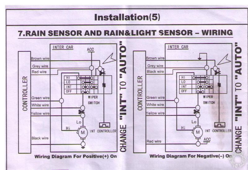
Yay for perseverance! If anyone is wanting to add Rain Sensing Wipers to their Spark it's dead easy once you've worked out the wiring.
The kit is available here...
From the "Wiper" side of the module. The wiring is connected to the car as follows.
Black - Earth (the car itself)
Green - Connects to the White wire from the Wiper control loom.
Red - Acc.
Grey - Acc.
Brown - Connects to the Purple wire from the Wiper control loom.
For the next two you'll need to cut the Yellow/Brown wire going to the Wiper control loom. Be sure to leave enough wire at both ends to strip and properly solder and either tape or cover with shrinktube.
Yellow - Connects to the Motor side of the Yellow/Brown wire from the Wiper control loom.
White - Connects to the Switch side of the Yellow/Brown wire from the Wiper control loom.
Remember to Solder ALL electrical connections and use good quality electrical tape to cover the joints or shrinktube. I prefer shrinktube over the soldered joints then I cover the entire new wiring with a spiral of black electrical tape to make it into a neat loom.
Hope that assists somebody!
------------- Cheers
Dave
Posted By: gregr72481
Date Posted: May 06, 2016 at 4:30 PM
Hey All. I am looking to install a Bazooka 8 in Bass Tube to add some lows in my 2014 spark. The Bazooka comes with a easy connect harness where all connections are made in the back of the factory radio.
My question is I need to connect to some wires in the back of the MyLink Stereo and I want to make sure I connect to correct wires. I know the diagram is listed above for this vehicle, but I am still kind of confused.
Instructions for the Bazooka harness say:
Red (+) 12V Power turns on when ignition/accessory is on.
Blue/White Turns on remote accessories (amplifiers, etc)
If there is no Remote Amplifier wire, you can use the power antenna wire.
The other wires on the harness are for speaker input connections which I understand.
I need help with this Red and Blue/White wire. What factory wires listed above would work for these connections?
Thanks for any help in advance.
-------------
Greg
"Long live GM - The heartbeat of America"
|