2012 Volvo S60 Alarm/Remote Start Wiring
Printed From: the12volt.com
Forum Name: Vehicle Wiring Information & File Requests
Forum Discription: Request Car Alarm, Car Stereo, Cruise Control, Remote Starter, Navigation, Mobile Video, and Other Vehicle Specific Wiring Info, Manuals, Tech Tips
URL: https://www.the12volt.com/installbay/forum_posts.asp?tid=141038
Printed Date: April 19, 2026 at 7:02 AM
Topic: 2012 Volvo S60 Alarm/Remote Start Wiring
Posted By: xraytedrick
Subject: 2012 Volvo S60 Alarm/Remote Start Wiring
Date Posted: March 19, 2016 at 6:48 PM
Hello. I'd like to request the wiring diagram for a 2012 Volvo S60. Thank you richard
-------------
Rick
Replies:
Posted By: wirewise
Date Posted: March 19, 2016 at 6:55 PM
You didn't say which wiring you were requesting, but here is the remote start info.
VOLVO / S60 / 2012 / Remote Start
12volts RED / black (50A) + CEM behind glove box, green 2 pin plug, pin 1
Starter blue (push-button start) + start-stop switch or CEM behind glove box, blue 76 pin plug, pin 3
Second Starter N/A
Ignition gray/black (for ignition sense only) + CEM behind glove box, green 76 pin plug, pin 63
Second Ignition N/A
Third Ignition N/A
Accessory GREEN/ orange (for accessory sense only) + front 12V outlet
Second Accessory N/A
Keysense N/A
Power Lock gray/purple - Driver Door Module, 24 pin plug, pin 14
Power Unlock PURPLE / black - Driver Door Module, 24 pin plug, pin 15
Lock Motor PURPLE / green 5 wire Driver Door Module, 22 pin plug, pin 3
Unlock Motor blue/green 5 wire Driver Door Module, 22 pin plug, pin 4
Parking Lights+ grn/og (LF), gry/rd (RF); pur/gn (LR), yel/bk (RR) + CEM, green 76 pin plug, pins 18, 15; brown 76 pin plug, pins 49, 47
Parking Lights- (LIN bus)
Hazards gray/red - hazard switch or CEM behind glove box, blue 76 pin plug, pin 13
Turn Signal(L) blue/green (F); gray/orange (R) + CEM, green 76 pin plug, pin 4; brown 76 pin plug, pin 44
Turn Signal(R) yellow/purple (F); GREEN/ orange (R) + CEM, green 76 pin plug, pin 66; brown 76 pin plug, pin 69
Reverse Light GREEN/ brown + CEM behind glove box, brown 76 pin plug, pin 73
Door Trigger GREEN/ purple - N.C. CEM behind glove box, brown 76 pin plug, pin 11
Dome Supervision gray/black - CEM behind glove box, black 20 pin plug, pin 14
Trunk/Hatch Pin yellow/orange - N.C. CEM behind glove box, brown 76 pin plug, pin 30
Hood Pin blue/orange - N.C. CEM behind glove box, green 76 pin plug, pin 39
Trunk/Hatch Release gray / YELLOW (rear handle switch) - CEM behind glove box, brown 76 pin plug, pin 24
Power Sliding Door N/A
Factory Alarm Arm (factory remote only)
Factory Alarm Disarm (see disarm no unlock)
Disarm No Unlock (transponder and push-button start)
Tachometer grn/blu, gry/yl, pur/gy, yel/og, blu/rd, or grn/wh ac any fuel injector, 2 pin plug, pin 2
Wait to start N/A
Brake Wire PURPLE / white + brake switch or CEM behind glove box, brown 76 pin plug, pin 45
Parking Brake (electric parking brake)
Horn Trigger PURPLE / green - CEM behind glove box, green 76 pin plug, pin 11
Memory Seat 1 (switch is part of module)
Memory Seat 2 (switch is part of module)
Memory Seat 3 (switch is part of module)
-------------
~wirewise~
Verify all wiring with your meter before making any connections!
Posted By: xraytedrick
Date Posted: March 20, 2016 at 9:10 AM
Would you have wiring information for the rear defroster?
Thanks
-------------
Rick
Posted By: xraytedrick
Date Posted: March 21, 2016 at 8:20 PM
Thank you for the wiring information. I have an idatalink ads alca module hardwired to a python 4106 remote start. Remote start is working well. When unlocking the doors the alarm is deactivated. When I lock the doors the alarm does not reactivate. When I try to open the trunk the alarm goes off. Do I need to double pulse to deactivate the alarm?
-------------
Rick
Posted By: xraytedrick
Date Posted: March 22, 2016 at 8:46 PM
I have a question about the disarm no unlock. Do I use the disarm output on the remote start to trigger two relays. One relay going to the push to start and the second to the immobilizer?
The immobilizer has three pins:
Pin 1 12volt
pin 2 data
pin 3 ground
Pin 2's wire is cut and the idatalink is connected to each wire end.
If i need to send the disarm signal to the immobilizer, which wire is it connected to?
Thank you
-------------
Rick
Posted By: xraytedrick
Date Posted: March 24, 2016 at 8:20 AM
Volvo wiring diagram shows rear defroster wire at the cem behind the glove box. When testing the wire, it goes from 12 volts to 0.3 volts and stays there. I understand i would set the r/s to latched defroster but am concerned the voltage does not drop completely to 0. Would I still set it up as a negative trigger with a relay from r/s?
Thank you
-------------
Rick
Posted By: xraytedrick
Date Posted: March 24, 2016 at 9:00 AM
Any help would be greatly appreciated.
Thank you
-------------
Rick
Posted By: xraytedrick
Date Posted: March 24, 2016 at 9:35 AM

I've uploaded an image of the wiring diagram if it helps.
------------- Rick
Posted By: xraytedrick
Date Posted: March 24, 2016 at 12:28 PM
I would like to wire the rear defroster on my volvo. I have a python 4106 remote start. I metered the wire coming from the CEM (yellow red C2:2) and found it rests at 12 volts and drops to 0.3 volts when defroster is activated. It seems to work like a negative trigger except i am concerned about the the 0.3 volt reading instead of 0. Is this a problem or can i use a relay to trigger this wire from the remote start?
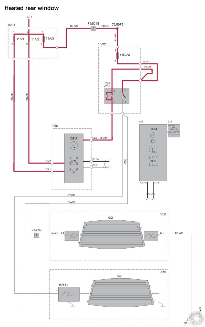
------------- Rick
Posted By: davep.
Date Posted: March 24, 2016 at 11:01 PM
You can take the yel/red to 0-volts. It will be fine.
The .3 V you see is the result of low (in this case 2.4 ohms)internal resistance of semi-conductors. They are not zero ohms resistance to ground.
Posted By: xraytedrick
Date Posted: March 25, 2016 at 10:50 PM
Thanks davep
-------------
Rick
|