2015 Ford 250 Alarm/Remote Start Wiring
Printed From: the12volt.comForum Name: Vehicle Wiring Information & File Requests
Forum Discription: Request Car Alarm, Car Stereo, Cruise Control, Remote Starter, Navigation, Mobile Video, and Other Vehicle Specific Wiring Info, Manuals, Tech Tips
URL: https://www.the12volt.com/installbay/forum_posts.asp?tid=141395
Printed Date: April 13, 2026 at 9:35 AM
Topic: 2015 Ford 250 Alarm/Remote Start Wiring
Posted By: albertvivo
Subject: 2015 Ford 250 Alarm/Remote Start Wiring
Date Posted: June 12, 2016 at 7:36 AM
Does anyone have the wiring diagram for an alarm install on a 2015 Ford 250?
Replies:
Posted By: geepherder
Date Posted: June 12, 2016 at 7:18 PM
https://readyremote.com/main.asp?action=select&yr=27472&product=Remote%20Start&make=Ford&model=F250
-------------
My ex once told me I have a perfect face for radio.
-------------
My ex once told me I have a perfect face for radio.
Posted By: tonanzith
Date Posted: June 26, 2016 at 12:25 AM
2015 Ford F250 DirectWire Vehicle Information
All Products
Item Wire Color Polarity Wire Location
12 Volts red (125A) + BCM in passenger kick, black 1 pin plug (G), pin 1
Second 12 Volts GREEN/ red (15A) + ignition switch, black 7 pin plug, pin 4
Starter blue/white + ignition switch, black 7 pin plug, pin 7
Second Starter N/A
Ignition WHITE/ orange + ignition switch, black 7 pin plug, pin 1
Second Ignition N/A
Third Ignition N/A
Accessory PURPLE / green + ignition switch, black 7 pin plug, pin 6
Second Accessory N/A
Third Accessory N/A
Keysense blue/gray + ignition switch, black 7 pin plug, pin 5
Data Bus PURPLE / gray (TX); yellow/orange (RX) data PATS Transceiver on ignition switch, black 4 pin plug, pins 3, 4
Can Bus High gray/orange (MS CAN); WHITE/ blue (HS CAN) data data link connector, black 16 pin plug, pins 3, 6
Can Bus Low PURPLE / orange (MS CAN); white (HS CAN) data data link connector, black 16 pin plug, pins 11, 14
Can Bus Sw N/A
Power Lock blue/green - driver kick or BCM in passenger kick, black 26 pin plug (C), pin 6
Power Unlock yellow/purple - driver kick or BCM in passenger kick, black 26 pin plug (C), pin 8
Lock Motor gray/brown 5 wire BCM in passenger kick, 32 pin plug (D), pin 26
Driver Unlock Motor blue/green 5 wire BCM in passenger kick, 32 pin plug (D), pin 21
Passenger Unlock Motor PURPLE / gray 5 wire BCM in passenger kick, 32 pin plug (D), pin 31
Parking Lights (-) yel/org (park lts); blk/gry (sw gnd)(TechDoc 1096) - and open headlight switch, gray 10 pin plug, pins 2, 3
Parking Lights (+) yellow/blue + BCM in passenger kick, gray 10 pin plug (E), pin 6
Hazards BROWN / yellow - hazard switch or BCM in passenger kick, black 52 pin plug (B), pin 32
Turn Signal (Left) blue/green (F); gray/brown (R) + BCM, green 26 pin plug (F), pin 8; 32 pin plug (D), pin 12
Turn Signal (Right) yellow/purple (F); PURPLE / orange (R) + BCM, green 26 pin plug (F), pin 7; 32 pin plug (D), pin 15
Headlight yellow/blue (headlight); BLACK/ gray (switch grnd) - and open headlight switch, gray 10 pin plug, pins 7, 3
AutoLights PURPLE / green (interrupt to turn off autolights) - headlight switch, gray 10 pin plug, pin 4
Reverse Light blue/white + BCM in passenger kick, 32 pin plug (D), pin 13
Left Front Door Trigger GREEN/ purple - N.C. BCM in passenger kick, black 26 pin plug (C), pin 9
Right Front Door Trigger white - N.C. BCM in passenger kick, blk 26 pin plug (C), pin 5
Left Rear Door Trigger green - N.C. BCM in passenger kick, blk 26 pin plug (C), pin 20
Right Rear Door Trigger yellow - N.C. BCM in passenger kick, blk 26 pin plug (C), pin 21
Dome Supervision gray/purple (dome lamp); purple (puddle lamp) + BCM, gray 12 pin plug (A), pin 1; black 26 pin plug (C), pin 1
Trunk/Hatch Pin N/A
Rear Glass Pin N/A
Hood Pin blue/orange - N.C. BCM in passenger kick, green 26 pin plug (F), pin 2
Trunk/Hatch Release N/A
Trunk Release Motor N/A
Fuel Door Release N/A
Power Sliding Door (Left) N/A
Power Sliding Door (Right) N/A
Factory Alarm Arm PURPLE / green and YELLOW /GREEN (driver door keypad) both - driver kick or BCM in passenger kick, blk 26 pin plg (C), pins 18, 11
Factory Alarm Disarm (see disarm no unlock)
Disarm No Unlock (transponder, ignition, and acc; see TechDoc 1098)
Trunk Alarm Shunt N/A
Tachometer blue ac Customer Access Harness above driver kick, taped to wiring harness
On models without the Customer Access Harness, go to any fuel injector and use the wire that is not blue (gasoline), or use the camshaft position sensor, which is WHITE/ green at the Powertrain Control Module on passenger side of engine, middle, black 98 pin plug, pin 32 (diesel).
Wait to Start N/A
Neutral Safety N/A
Clutch Pedal blue/orange - clutch switch, gray 6 pin plug, pin 1
Fuel Pump yellow/purple (gasoline) - BCM in passenger kick, green 26 pin plg (F), pin 6
On diesel models, use BROWN / white (+) at the Inertia Fuel Shutoff Switch above the passenger kick, gray 3 pin plug, pin 1.
Rear Defroster WHITE/ orange - latched right of steering column, black 59 pin plug, pin 15
Mirror Defroster (same as rear defroster)
Left Front Heated Seat (MS CAN)
Right Front Heated Seat (MS CAN)
Speed Sense PURPLE / orange ac Customer Access Harness above driver kick, taped to wiring harness
Brake Wire PURPLE / white + brake switch or BCM in passenger kick, black 52 pin plug (B), pin 28
Parking Brake WHITE/ purple - Customer Access Harness above driver kick, taped to wiring harness
Horn Trigger PURPLE / green - horn switch or BCM in passenger kick, black 52 pin plug (B), pin 33
Wipers (LIN bus)
Left Front Window (Up/Down) (motor is part of module)
Right Front Window (Up/Down) (motor is part of module)
Left Rear Window (Up/Down) blue/orange - yellow A driver kick, door harness
Right Rear Window (Up/Down) gray/purple - BROWN / green A driver kick, door harness
The power sliding rear window open/close are PURPLE / brown - yellow/orange (5 wire) at the overhead console switch, gray 12 pin plug, pins 4 - 9.
Sun Roof (Open/Close) PURPLE / brown - yellow/orange (func w/ign on only) - overhead console switch, gray 12 pin plug, pins 6 - 8
Sun Roof (Limit/Close) N/A
Memory Seat 1 PURPLE / white - driver kick, door harness
Memory Seat 2 yellow - driver kick, door harness
Memory Seat 3 N/A
Radio 12V gray/red + radio, gray 24 pin plug, pin 1
Radio Ground BLACK/ blue - radio, gray 24 pin plug, pin 13
Radio Ignition gray/blue (base audio); (MS CAN on premium audio) + radio, gray 24 pin plug, pin 2
Radio Illumination PURPLE / gray (dimmer) + radio, gray 24 pin plug, pin 3
Factory Amp Turn-on PURPLE / red + radio, 26 pin plug, pin 18
Power Antenna N/A
Left Front Speaker (+/-) white - WHITE/ brown, or green - gray +,- radio, gray 24 pin plug, pins 8 - 21, or 22 - 10
On models with amplifier, the speaker wires are white - WHITE/ brown (woofer); GREEN/ orange - gray/orange (tweeter) at the amplifier under the rear seat, gray 16 pin plug, pins 2 - 10; 3 - 11.
Right Front Speaker (+/-) WHITE/ purple - WHITE/ orange, or purple - yellow +,- radio, gray 24 pin plug, pins 11 - 12, or 23 - 11
On models with amplifier, the speaker wires are WHITE/ purple - WHITE/ orange (woofer); PURPLE / orange - yellow/orange (tweeter) at the amplifier under the rear seat, gray 16 pin plug, pins 6 - 14; 7 - 15.
Left Rear Speaker (+/-) WHITE/ green - BROWN / yellow +,- radio, gray 24 pin plug, pins 9 - 22, or 21 - 9
On models with amplifier, the speaker wires are WHITE/ green - BROWN / yellow at the amplifier under the rear seat, gray 16 pin plug, pins 4 - 12.
Right Rear Speaker (+/-) BROWN / white - BROWN / blue +,- radio, gray 24 pin plug, pins 10 - 23, or 24 - 12
On models with amplifier, the speaker wires are BROWN / white - BROWN / blue at the amplifier under the rear seat, gray 16 pin plug, pins 8 - 16.
Center Channel (+/-) green - gray / YELLOW +,- amplifier under rear seat, gray 16 pin plug, pins 1 - 9
Subwoofer (+/-) PURPLE / green - GREEN / WHITE (preamp) +,- radio, 26 pin plug, pins 4 - 17
On models with amplifier, the speaker wires are PURPLE / green - GREEN / WHITE (1); WHITE/ brown - PURPLE / orange (2) at the amplifier under the rear seat, blue 16 pin plug, pins 1 - 9; 2 - 10.
Aux. Audio Input Left (+/-) blue - YELLOW /GREEN (without SYNC) +,- radio, gray 16 pin plug, pins 7 - 8
Aux. Audio Input Right (+/-) blue/green - WHITE/ green (without SYNC) +,- radio, gray 16 pin plug, pins 6 - 14
RSE Video (+/-) WHITE/ green - BROWN / purple (rear camera video) +,- SYNC Module/display, blk 54 pin plug, pins 14 - 15
RSE Audio Left (+/-) blue - gray/orange (SYNC audio) +,- radio, gry 16P plg, pins 1-2; 26P plg, pins 12-25
RSE Audio Right (+/-) PURPLE / green - BROWN / white (SYNC audio) +,- radio, gry 16P plg, pins 9-10; 26P plg, pins 13-26
Satellite Radio 12 Volts (built into radio)
Satellite Radio Ground N/A
Satellite Radio Ignition N/A
Satellite Radio Antenna N/A
Satellite Audio Left (+/-) N/A
Satellite Audio Right (+/-) N/A
Item Size Depth Location
Headunit double DIN center of dash
Left Front Speaker 6 x 8 4 left front door
Left Front Tweeter left front door
Right Front Speaker 6 x 8 4 right front door
Right Front Tweeter right front door
Left Rear Speaker 6 x 8 3 left rear door or left rear pillar
Left Rear Tweeter left rear door
Right Rear Speaker 6 x 8 3 right rear door or right rear pillar
Right Rear Tweeter right rear door
Center Channel N/A
-------------
Gary Sather
Posted By: johnnygaloshes
Date Posted: November 15, 2016 at 12:56 AM
Anyone know if this is the same for a 2016 F-250 Super Duty? I'm looking to install a stereo.
Posted By: liczbinski
Date Posted: February 02, 2017 at 3:34 PM
Does anyone have an electrical diagram for installing a remote start/ push button start on a 2017 F-150?
-------------
MJL
-------------
MJL
Posted By: eddieschopshop
Date Posted: February 03, 2017 at 1:05 PM
liczbinski-you might want to start a NEW POST since the original tittle calls for 2015 f250..
Posted By: onlylive_once
Date Posted: November 12, 2017 at 6:44 PM
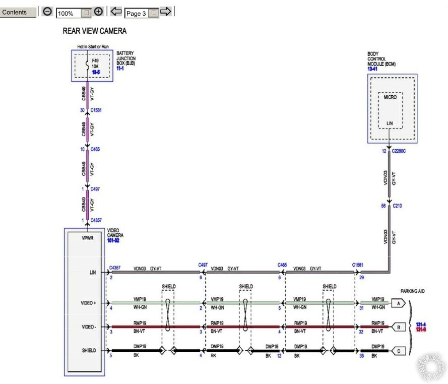
I have a 2008 f250 with a tail gate from a 2015. The schematic shows the camera has a hot but not a ground it shows the grey/violet goes to bcm. I'm installing pioneer double din and can't get the camera to switch on.
How do I get this camera to power up? I've tried putting power and ground to this wire and nothing. I'm using reverse light for power trigger and have 12 volts at the connection. I spliced the camera outputs to an rca to hook to radio but that's easy 2 wires no issues with that. I used telephone line splices to splice the rca for a low resistance quality connection.
How do I get this camera to power up? I've tried putting power and ground to this wire and nothing. I'm using reverse light for power trigger and have 12 volts at the connection. I spliced the camera outputs to an rca to hook to radio but that's easy 2 wires no issues with that. I used telephone line splices to splice the rca for a low resistance quality connection.
Posted By: tonanzith
Date Posted: November 12, 2017 at 7:36 PM
Thought these were 5v cameras?
-------------
Gary Sather
-------------
Gary Sather
Posted By: onlylive_once
Date Posted: November 12, 2017 at 7:44 PM
My understanding since i posted this, the bcm is a negative trigger so not sure how it would limit voltage based on the schematic. This has me stumped. No reason it shouldn't be working.