2016 Honda CR-V Touring Alarm/Remote Start Wiring
Printed From: the12volt.com
Forum Name: Vehicle Wiring Information & File Requests
Forum Discription: Request Car Alarm, Car Stereo, Cruise Control, Remote Starter, Navigation, Mobile Video, and Other Vehicle Specific Wiring Info, Manuals, Tech Tips
URL: https://www.the12volt.com/installbay/forum_posts.asp?tid=141840
Printed Date: April 18, 2026 at 11:53 PM
Topic: 2016 Honda CR-V Touring Alarm/Remote Start Wiring
Posted By: alarmgeek
Subject: 2016 Honda CR-V Touring Alarm/Remote Start Wiring
Date Posted: October 09, 2016 at 12:06 AM
I am in need of the wiring information for a 2016 Honda CRV touring model.
I am not sure how involved this will be to add an alarm / remote start with all the new electronics that are in the latest touring.
I put a viper in my last CRV (2009) and it has worked flawless for 7 years. Time to upgrade.
Replies:
Posted By: alarmgeek
Date Posted: November 02, 2016 at 12:50 AM
No help?
Does anyone have the wire colors and locations, that would really help.
I believe the 2015 is the same as the 2016 so if you have it for CRV 2015 with PTS it would be appreciated.
Posted By: kreg357
Date Posted: November 03, 2016 at 8:33 AM
Being as you have PTS and will need a full featured bypass module, the easiest way to get the wires locations and color
for your R/S w/Alarm install would be from the actual bypass module install diagram. I use iDatalink modules and the
2015 and 2016 CR-V Touring editions are listed as the same ( so are the non-Touring PTS models ). Go to the iDatalink
WEB site and look up your CR-V. The Type 8 install diagram gives you pretty much everything including the Parking Lights.
You won't need the Horn if you're installing and alarm system but the car comes with a factory alarm. The only issue
will be that the R/S will shut down as soon as a door is opened. That's just they way it works. Most of the wiring
is behind the glove box. A bit cramped and not much room to place the R/S modules.
iDatalink : https://cdncontent2.idatalink.com/corporate/Content/Manuals/DL-HA6/ADS-AL(DL)-HA6-EN_20160805.pdf
Fortin does it a little differently (locks) but has photo's to aid with the install. Fortin EVO-ALL bypass install :
https://fortin.ca/download/34041/evo-all_honda_crv_pts_2015_34041_h20151007.pdf
-------------
Soldering is fun!
Posted By: alarmgeek
Date Posted: November 03, 2016 at 10:25 AM
I have that, it came with the alarm. What is missing is the rest of the wires that are required. What is missing and not typical since this is push to start, no key switch is ignition 1, ignition 2, accessory, light, start.
I have just started the install and will find the wires the old way with a meter if nothing is posted. One way or another I will get it done. When complete I will post a complete list for the next guy.
Posted By: kreg357
Date Posted: November 03, 2016 at 11:09 AM
You are not using a bypass module? What brand model R/S w/Alarm are you installing?
-------------
Soldering is fun!
Posted By: alarmgeek
Date Posted: November 05, 2016 at 11:09 AM
I am installing an Excalibur 2060 with the ol-blade-all. I had been looking at the wrong wiring diagrams that had a lot of wiring points duplicating, that made the work overwhelming. As it turned out most everything is through the data lines.
It is installed and working so I must have done most of it right ;)
I am working on a complete wire chart that includes ALL connection points, I will get it posted in a few days.
Posted By: alarmgeek
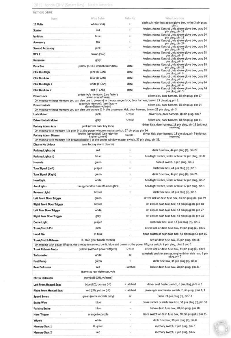
Date Posted: November 09, 2016 at 3:00 PM
I hope this helps others.
Posted By: daflipcyde
Date Posted: November 09, 2016 at 5:57 PM
Thanks for the wiring diagram.
Posted By: mikeremotestart
Date Posted: October 22, 2017 at 12:32 PM
Hi,
I am using xpress kit by pass module with Viper 5706 remote starter:
In remote start which wire is GWR(Status) - in xpressKit manual, it says to connect to GWR Input in the bypass module.
Also, Can I not use the accessory 1 and 2 wire? I don't really need them.
In xpresskit module, in red harness, there wire# PTS Output (Red/black), do I required to connect that?
-------------
Mike
Posted By: alarmgeek
Date Posted: October 22, 2017 at 2:51 PM
GWR = Ground While Running, this may be all you need, if not tell me which side, 5706 remote starter or express kit, you are looking for the GWR on.
PTS = Push To Start, whether you need this depends on the installation, car / model.
Posted By: howie ll
Date Posted: October 22, 2017 at 4:47 PM
Alarmgeek, nice work.
-------------
Amateurs assume, don't test and have problems; pros test first. I am not a free install service.
Read the installation manual, do a search here or online for your vehicle wiring before posting.
Posted By: mikeremotestart
Date Posted: October 24, 2017 at 2:02 PM
HI,
Can Someone verify the Xpress kit wiring to car (Dball2 connection) for Honda CRV 2016, push to start.
I have named D1 - 10pin connection, D2 - 12 pin connected, D3- 14pin connector of xpresskit bypass module.
D2/4 PTS Output to Car side, PTS Pine 8
D2/10 Immobilizer Data to Immo Data pin 21 (Yellow)
D3/3 HS CAN High to B-CAN High Pin 6(of pin 28)
D3/4 HS CAN Low to B-CAN Low Pin 7 (of pin 28)
D3/5 FT CAN High to F-CAN High Pin 4 (of pin 24)
D3/6 FT CAN Low to F-CAN Low Pin 5 (of pin 24)
D3/8 Ignition Interrupt (Connection side) to Ignition Pin 28
D3/9 Ignition Interrupt (Vehicle side) Ignition other side of the ignition wire
Remote wiring Viper 5706 (Very Important)
H3/1 Ignition 1 input/output (Pink) (+) to Pin 11 (of 24) Igntion (+) (Blue)
H3/2 Fused Ignition 2/ Flex Relay Input 87 12V Constant (White)
H3/3 Accessory Output, Orange (+) to Accessory 1 (Tan), Pin 24 of 24.
H3/4 Starter Output (Car side of the starter kit)
H3/5 - Starter Output (Key side of the starter kit)
Not sure about H3/4 and H3/5 connection. Xpress kit Say that connectto Pin 18 of the starter of the car. I already cut ignition wire. Do i have to cut the starter output wire or which one to connect to starter of the car. Any suggestion
H3/6 Fused Ignition 1 Input Connect to 12V Constant (White)
H3/7 Ignition 2 (+)/Flex Relay Output should I use this as 2nd accessory. Do i need to connect to any car wire or viper remote wire?
H3/8 - not using it.
H3/9 Fused Accessory/Starter Input to 12V Constant
H2/13 (of 24 pin) Black/white Neutral Safety to ground wire of the remote starter.
H1/5 (of 6 pin) Parking light output to Parking light of Car (Gray) (Pin 8 of 24)
Any suggestions appreciated!
-------------
Mike
Posted By: alarmgeek
Date Posted: October 24, 2017 at 3:40 PM
Did you follow this?
https://www.the12volt.com/installbay/forum_posts.asp?tid=141840#721460
Posted By: jdwolf
Date Posted: November 09, 2018 at 2:03 AM
Don't mean to revive an old thread, but any help would be greatly appreciated. I have a 2015 Honda CR-V with Push To Start, and here follows what I'm trying to get installed and hooked up.
Compustar CM-7000
Idatalink Blade-AL
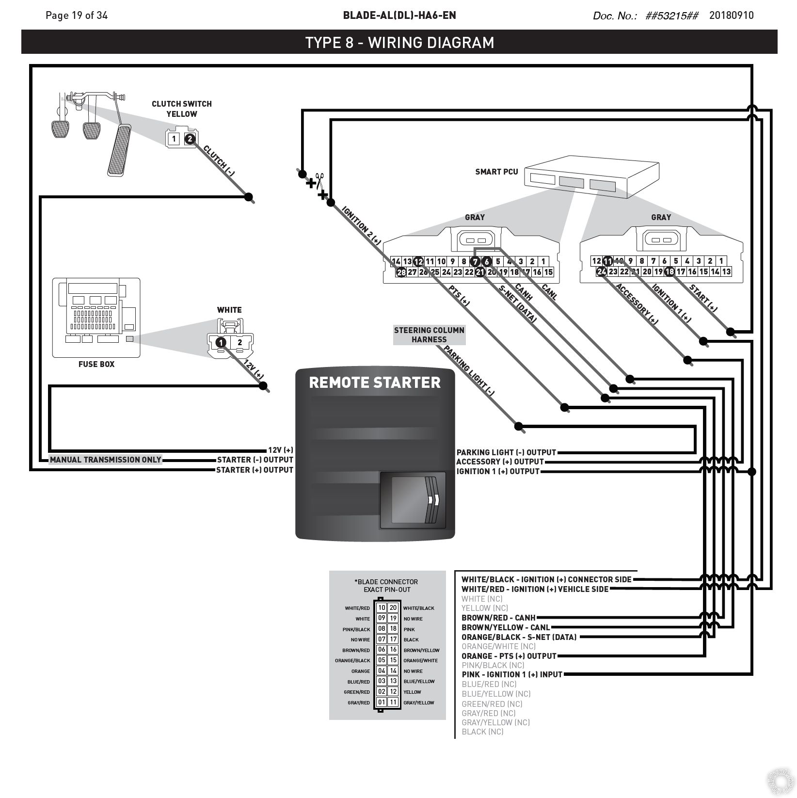
I'm having trouble understanding the two wires that pertain to wiring up to "Ignition 2". There is a white/red wire and white/black wire that needs to be hooked up in this area.
Here's my golden question one wire needs to be on the "connector side" and the other on the "vehicle side." Could someone explain to me what is meant by "vehicle side?"
I believe this is the last wire I need to get wired up for me to get everything fired up and working. I also feel like this is a stupid question, stupid answer scenario! So I do apologize!
Also thank you for the wiring diagram as I was able to find the 12v wire and parking lights since my guides did not specify the location of them.
Posted By: geepherder
Date Posted: November 09, 2018 at 7:15 AM
Okay, so it looks like instead of starter kill this uses "ignition kill". Many installers prefer not to cut any wire other than the starter to eliminate another point of failure. If you cut the starter wire and something goes wrong, the vehicle simply won't start. If you cut an ignition wire, during a failure, the engine could potentially die while you're driving down the highway.
If you don't feel you need this feature, you can connect both wires to ignition without cutting. You can always wire in your own starter kill relay for added protection:
https://www.the12volt.com/relays/starter-interrupt-diagrams.asp#sk1
If you choose you want this feature, you would cut this wire close to the ignition switch. The end of the wire that goes leads back to the ignition switch would be the "connector side". The other cut end would be the "vehicle side".
-------------
My ex once told me I have a perfect face for radio.
|