2002 Blazer Remote Start- Starter Wire
Printed From: the12volt.com
Forum Name: Vehicle Wiring Information & File Requests
Forum Discription: Request Car Alarm, Car Stereo, Cruise Control, Remote Starter, Navigation, Mobile Video, and Other Vehicle Specific Wiring Info, Manuals, Tech Tips
URL: https://www.the12volt.com/installbay/forum_posts.asp?tid=143804
Printed Date: April 17, 2026 at 4:29 AM
Topic: 2002 Blazer Remote Start- Starter Wire
Posted By: 7ronin
Subject: 2002 Blazer Remote Start- Starter Wire
Date Posted: November 22, 2017 at 5:55 PM
Hello,
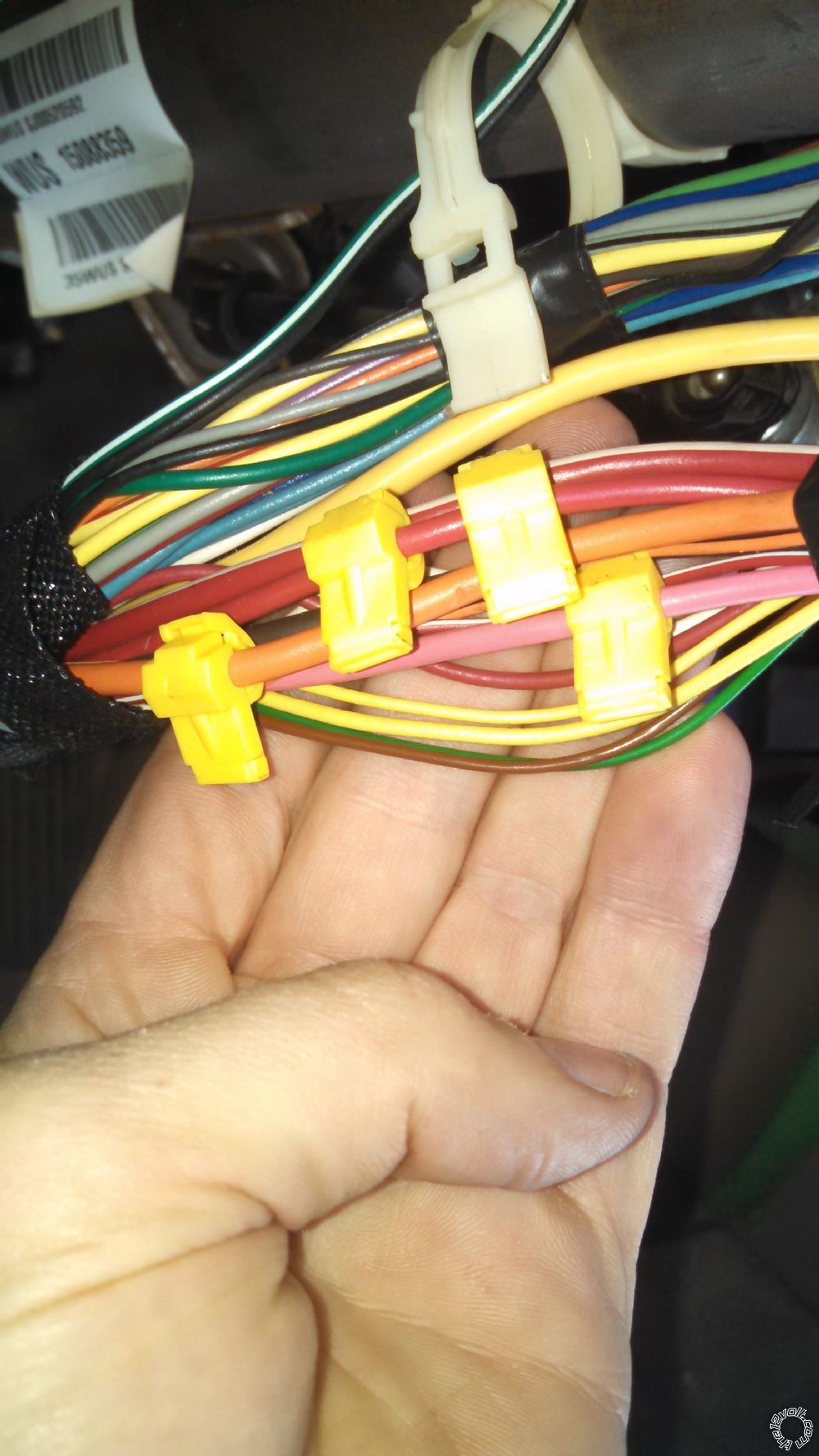
I am attempting to install a remote start kit in my 2002 Blazer Automatic and the kit I have (Crimestopper RS4-G5) and I'm having trouble locating the yellow starter wire that is supposed to be in the ignition harness. There are two small yellow wires in this harness (small gauge, like 16-18). One is larger than the other and both go to the ignition switch but neither of these wires look like what I have seen in the install diagrams here. The picture Below are the yellow wires I am talking about (the large yellow "wire" by my middle finger is the airbag wire)- Can anyone offer any advice as to what wire is the starter wire that I need to connect to? Thanks
Replies:
Posted By: tdbaker021
Date Posted: November 22, 2017 at 7:44 PM
You can check it with a DMM. This wire will have 12V current when the key is in the start position.
Posted By: 7ronin
Date Posted: November 22, 2017 at 7:54 PM
Thanks- I can definitely do that.
I wonder why the start wire is so small on this model Blazer? My concern is that the remote start kit wire that I will be connecting to is like a 12ga wire. If the wire is just meant as a signal to show that the car is requesting starter crank I guess it OK.....
Posted By: tdbaker021
Date Posted: November 22, 2017 at 9:57 PM
It will be fine. I just installed one in my 2000 Silverado and that starter wire was smaller then then my 2006 Silverado starter wire.
Posted By: kreg357
Date Posted: November 23, 2017 at 2:20 AM
Just a note about your install...
I'm not sure from your vehicle description if this is a Trailblazer or an S-10 Blazer but...
There is a White IGN2 wire in the ignition harness that must be powered during a remote start or transmission
problems will occur. This White IGN2 wire is a slightly smaller gauge wire than the Pink IGN1 wire.
Also, there is a thick Red/White wire that is a +12V constant source. You should split the Crimestoppers
load between these two wires. From the photo, it looks like you have two T-Taps on the Red wire and none
on the Red/White wire.
I won't mention anything about your use of T-Taps....  ------------- Soldering is fun!
Posted By: 7ronin
Date Posted: November 23, 2017 at 9:07 AM
Ahh,
Appreciate the advice in the IGN-2 Wire. The instructions for this kit are sorely lacking- I have found several errors already and the kit stated to tap both into red 12v wire only. As far as the T-Taps go I'm not concerned- electronics industry uses these types of connections regularly (the are called insulation displacement connectors or IDC). I would not use them in anything but in-car environments as opposed to underhood etc. I also like the idea of being able to quickly remove any installed equipment. Lastly, the lack of decent instructions means that the removable spades on the T-Taps makes troubleshooting easier.
Again- much appreciated.
kreg357 wrote:
Just a note about your install...
I'm not sure from your vehicle description if this is a Trailblazer or an S-10 Blazer but...
There is a White IGN2 wire in the ignition harness that must be powered during a remote start or transmission
problems will occur. This White IGN2 wire is a slightly smaller gauge wire than the Pink IGN1 wire.
Also, there is a thick Red/White wire that is a +12V constant source. You should split the Crimestoppers
load between these two wires. From the photo, it looks like you have two T-Taps on the Red wire and none
on the Red/White wire.
I won't mention anything about your use of T-Taps....
Posted By: 7ronin
Date Posted: November 23, 2017 at 9:10 AM
tdbaker021 wrote:
It will be fine. I just installed one in my 2000 Silverado and that starter wire was smaller then then my 2006 Silverado starter wire.
I hear you but I'm still concerned- some wiring diagrams I have seen have labeled the two small yellow wires as part of the VATS system....
I ordered a factory schematic from Ebay and I'm going to see if I can verify what wires are what before I risk screwing up the VATS stuff and then having to replace the BCM etc.
Appreciate the help!
Posted By: kreg357
Date Posted: November 23, 2017 at 3:03 PM
You could also pull off the steering column covers and look at the actual ignition switch
harness connector where it plugs into the ignition switch and follow the wires from there.
Using a Digital MultiMeter is another option. Set to 20V DC. The Starter wire will only
show +12V when the key is in the START position. A Passlock 2 wire will show around 4.5V.
-------------
Soldering is fun!
Posted By: tdbaker021
Date Posted: November 23, 2017 at 3:52 PM
7ronin wrote:
tdbaker021 wrote:
It will be fine. I just installed one in my 2000 Silverado and that starter wire was smaller then then my 2006 Silverado starter wire.
I hear you but I'm still concerned- some wiring diagrams I have seen have labeled the two small yellow wires as part of the VATS system....
I ordered a factory schematic from Ebay and I'm going to see if I can verify what wires are what before I risk screwing up the VATS stuff and then having to replace the BCM etc.
Appreciate the help!
Always best to verify the wire with a DMM. Your starter wire will show 12V when the key is in the start position and the VATS will be much less. Is this vehicle a Trailblazer or S-10 Blazer?
Posted By: tdbaker021
Date Posted: November 23, 2017 at 3:52 PM
kreg357 wrote:
You could also pull off the steering column covers and look at the actual ignition switch
harness connector where it plugs into the ignition switch and follow the wires from there.
Using a Digital MultiMeter is another option. Set to 20V DC. The Starter wire will only
show +12V when the key is in the START position. A Passlock 2 wire will show around 4.5V.
Didn't see your reply until I posted mine lol
Posted By: 7ronin
Date Posted: November 23, 2017 at 4:24 PM
Sorry for my late response- Vehicle is a 2002 Blazer LS (Not a TrailBlazer).
I'll see if I can get them traced up to the switch tomorrow.
Appreciate the help!
tdbaker021 wrote:
7ronin wrote:
tdbaker021 wrote:
It will be fine. I just installed one in my 2000 Silverado and that starter wire was smaller then then my 2006 Silverado starter wire.
I hear you but I'm still concerned- some wiring diagrams I have seen have labeled the two small yellow wires as part of the VATS system....
I ordered a factory schematic from Ebay and I'm going to see if I can verify what wires are what before I risk screwing up the VATS stuff and then having to replace the BCM etc.
Appreciate the help!
Always best to verify the wire with a DMM. Your starter wire will show 12V when the key is in the start position and the VATS will be much less. Is this vehicle a Trailblazer or S-10 Blazer?
Posted By: shark mobile
Date Posted: November 23, 2017 at 8:48 PM
The best and only way you should determine the start wire is being at the ignition connector and metering voltage. 12v in the crank for a second and falls flat 0V when the vehicle starts.
-------------
Solder, tape, repeat!
Posted By: howie ll
Date Posted: November 25, 2017 at 11:55 AM
Interestingly enough, we aren't even allowed to use T-Taps in the UK!
Need I say more or do you want an explanation.
SOLDER!!
-------------
Amateurs assume, don't test and have problems; pros test first. I am not a free install service.
Read the installation manual, do a search here or online for your vehicle wiring before posting.
Posted By: shark mobile
Date Posted: November 25, 2017 at 7:29 PM
In my career I have seen countless times that t-taps have failed...melted, expanded and lost connection, and just improperly connected. Solder is faster, more reliable and permamnant. My personal preference is to do a modified western union and solder then tape. Its how I was taught and its how Ive taught my apprentices. Solder, tape, repeat lol
-------------
Solder, tape, repeat!
Posted By: kreg357
Date Posted: November 25, 2017 at 8:40 PM
That would make two +1's......  Soldering really is fun! ------------- Soldering is fun!
Posted By: howie ll
Date Posted: November 26, 2017 at 12:42 AM
And Shark's description is exactly how I'd do it.
-------------
Amateurs assume, don't test and have problems; pros test first. I am not a free install service.
Read the installation manual, do a search here or online for your vehicle wiring before posting.
|

 Soldering really is fun!