Print Page | Close Window

98 Toyota Camry Accessory Wire

Printed From: the12volt.com
Forum Name: Vehicle Wiring Information & File Requests
Forum Discription: Request Car Alarm, Car Stereo, Cruise Control, Remote Starter, Navigation, Mobile Video, and Other Vehicle Specific Wiring Info, Manuals, Tech Tips
URL: https://www.the12volt.com/installbay/forum_posts.asp?tid=144080
Printed Date: May 02, 2024 at 1:33 PM


Topic: 98 Toyota Camry Accessory Wire

Posted By: jewest
Subject: 98 Toyota Camry Accessory Wire
Date Posted: January 27, 2018 at 2:38 AM

Hey Guys,

Working on a 98 Camry XLE. Modules used - Viper 4105.2 / DEI 556U. First Viper I have ever used..

Issue is the car only remote starts with the key in either the accessory or ignition positions.

Fairly sure this is not an issue with the bypass since the security light does not flash when I have things connected right – further the key has to be set to ACC/Ignition – simply being inserted does not work.

Documentation here has been 100% accurate so far!! However I’m confused where it says “Accessory – Tests as Ignition”.. Does this mean the RS must be set to “Accessory Output = On during wait-to-start”?

I’m trying to program the viper using the valet button. Able to reach Menu 2 Feature 7 however while holding the valet button and pressing unlock on the fob to set Option 2 I get no led flash indication that option 2 was accepted as the manual indicates – and no change in behavior after. Is there a trick to this? Possibly feature lock?

At complete loss here. Would it be a valid test to simply cross Ignition 1 output with accessory output, or am I even going down the path to troubleshoot this?


Replies:

Posted By: jewest
Date Posted: January 27, 2018 at 4:56 PM
To provide additional information.. Aside from the "Tests as ignition" note I am also thinking accessory based on information from the Haynes manual.

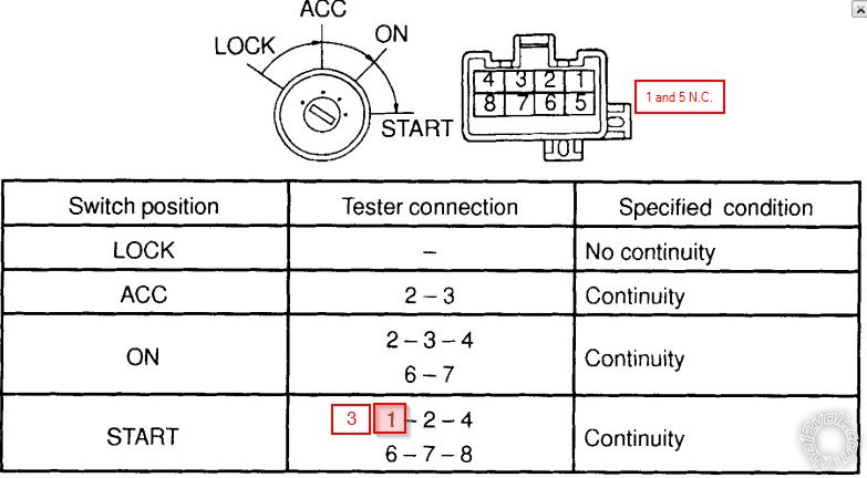
The Camry uses an 8 pin ignition harness with 6 wires in the harness actually connected. Pins 1 and 5 have no wiring but the continuity diagram shows the Start position passing continuity between 6 pins. Problem is it indicates pin 1 that is NC so I am pretty sure they meant Pin 3 for accessory.

posted_image

Since it seems like feature programming is locked and I do not have a BitWriter - ill try the previous note tonight (crossing Ignition 1 out with Accessory out). In the event this works ill have to keep it wired this way until I can find a shop with a bitwriter who's willing to reprogram it.


Posted By: kreg357
Date Posted: January 28, 2018 at 5:42 PM
Is this your current wiring?

Heavy gauge 6 Pin
1 RED (+) (30A) HIGH CURRENT 12V INPUT...................................White
2 PINK/WHITE (+) PROGRAMMABLE OUTPUT...............................Black/Yellow
3 RED (+) (30A) HIGH CURRENT 12 INPUT.....................................White/Red
4 ORANGE (+) (30 AMP) OUTPUT TO ACC CIRCUIT.......................Blue/Red
5 PURPLE (+) (30 AMP) OUTPUT TO STARTER CIRCUIT..............Red
6 PINK (+) (30 AMP) OUTPUT TO IGNITION CIRCUIT.....................Black/Red

-------------
Soldering is fun!


Print Page | Close Window