2013 Honda Pilot EX-L w/ Navigation, Factory Amp
Printed From: the12volt.com
Forum Name: Vehicle Wiring Information & File Requests
Forum Discription: Request Car Alarm, Car Stereo, Cruise Control, Remote Starter, Navigation, Mobile Video, and Other Vehicle Specific Wiring Info, Manuals, Tech Tips
URL: https://www.the12volt.com/installbay/forum_posts.asp?tid=146429
Printed Date: March 31, 2026 at 12:40 AM
Topic: 2013 Honda Pilot EX-L w/ Navigation, Factory Amp
Posted By: nola111
Subject: 2013 Honda Pilot EX-L w/ Navigation, Factory Amp
Date Posted: September 08, 2020 at 6:12 PM
I'm looking for the wiring diagram for the factory amp of a 2013 Honda Pilot EX-L with Navigation and 7-speaker system. I am wanting to integrate an AudioControl LC7i after the factory amp and need to understand what wires go to what speakers.
Replies:
Posted By: i am an idiot
Date Posted: September 08, 2020 at 7:49 PM
2013 Honda Pilot - North America
Wire Name: Left Front Speaker (+/-)
no photo
Note: On models with amplifier, the speaker wires are blue - red at the amplifier above passenger kick, gray 24 pin plug, pins 18 - 19. The tweeter wires are white/yellow - brown/black at the amplifier, gray 28 pin plug, pins 27 - 28.
2013 Honda Pilot - North America
Wire Name: Right Front Speaker (+/-)
no photo
Note: On models with amplifier, the speaker wires are red - brown at the amplifier above passenger kick, gray 24 pin plug, pins 20 - 21. The tweeter wires are red/white - brown/white at the amplifier, gray 28 pin plug, pins 14 - 13.
2013 Honda Pilot - North America
Wire Name: Left Rear Speaker (+/-)
no photo
Note: On models with amplifier, the speaker wires are red - blue at the amplifier above passenger kick, gray 24 pin plug, pins 23 - 22. The surround speaker wires are blue - gray at the amplifier, gray 24 pin plug, pins 10 - 11.
2013 Honda Pilot - North America
Wire Name: Right Rear Speaker (+/-)
no photo
Note: On models with amplifier, the speaker wires are red - blue at the amplifier above passenger kick, gray 24 pin plug, pins 7 - 6. The surround speaker wires are red - black at the amplifier, gray 24 pin plug, pins 9 - 8.
2013 Honda Pilot - North America
Wire Name: Center Channel (+/-)
no photo
Note: On models with amplifier, the speaker wires are black - pink at the amplifier above passenger kick, gray 24 pin plug, pins 17 - 16.
2013 Honda Pilot - North America
Wire Name: Subwoofer (+/-)
no photo
Note: On models with amplifier, the speaker wires are white - red at the amplifier above passenger kick, gray 24 pin plug, pins 15 - 14.
Posted By: nola111
Date Posted: September 09, 2020 at 6:16 AM
Amazing, thank you.
What part of Louisiana are you in?
Posted By: i am an idiot
Date Posted: September 09, 2020 at 9:32 AM
Gonzales/ B.R.
Posted By: nola111
Date Posted: September 09, 2020 at 9:38 AM
Cool, I'm in Metairie. I'll be working on my Pilot and my wife's Odyssey over the next several weekends. Looking forward to it!
Posted By: Custom_Jim
Date Posted: September 14, 2020 at 12:15 PM
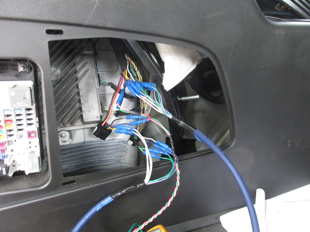
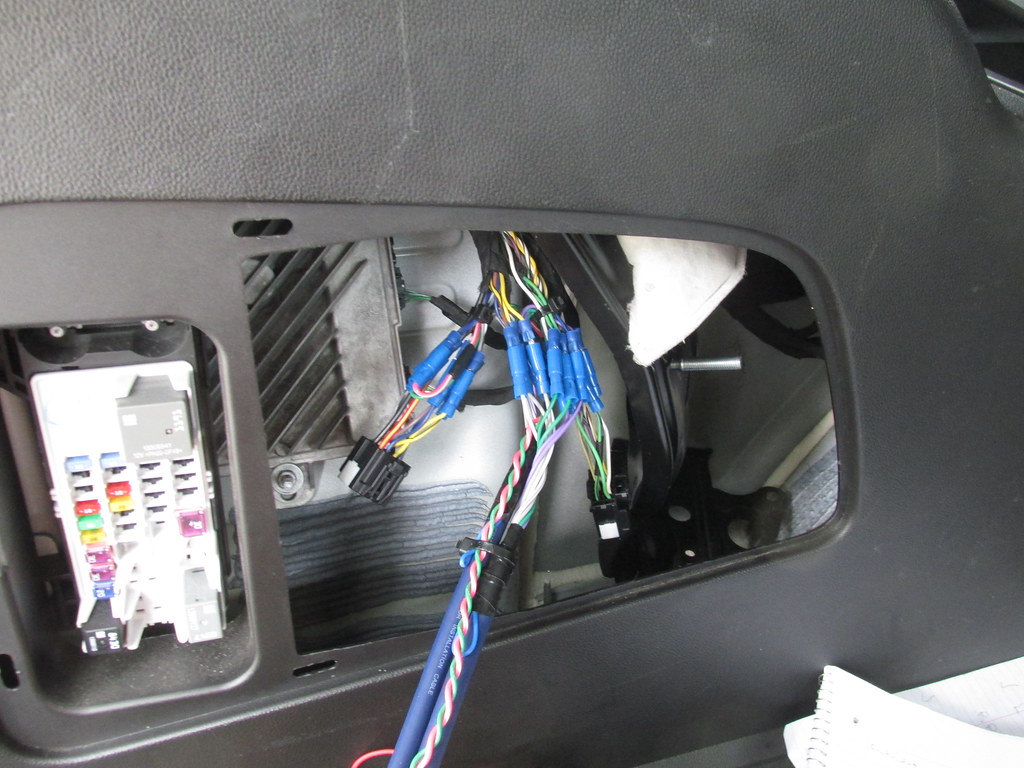
In another post that is now closed you were asking if wires needed to be cut and that you wanted to easily put it back to stock later. What I have done is a few inches out from the plug on the amplifier, cut the wires you need to and then on the end that goes to the speaker, crimp on a fully insulated male terminal and on the wire end off of the amplifier's output, crimp on a fully insulated female terminal. Later you can unplug what you have added onto these male and female terminals and then plug them back together. Having the male ends on the wire side that goes to the speaker allows you to easily pop the speaker off of a small AA battery.
Harness before modification
 Factory Wires Cut
 Male and Female ends crimped on and extension wiring plugged in
 Added wiring and connections cleaned up and tied up
Jim ------------- 1968 Chevy II Nova Garage Find 2012
1973 Nova Custom
1974 Spirit of America Nova
1973 Nova Pro-Street
Posted By: nola111
Date Posted: September 14, 2020 at 12:47 PM
Great work and thanks for posting here!!
Posted By: nola111
Date Posted: September 15, 2020 at 2:45 PM
Custom_Jim wrote:
In another post that is now closed you were asking if wires needed to be cut and that you wanted to easily put it back to stock later. What I have done is a few inches out from the plug on the amplifier, cut the wires you need to and then on the end that goes to the speaker, crimp on a fully insulated male terminal and on the wire end off of the amplifier's output, crimp on a fully insulated female terminal. Later you can unplug what you have added onto these male and female terminals and then plug them back together. Having the male ends on the wire side that goes to the speaker allows you to easily pop the speaker off of a small AA battery.
Hey @Custom_Jim - this might be a silly question, but did you plug the connector back into the factory amp or leave it unplugged? I was just wondering if there is a need for it to get plugged back in so the factory amp still outputs signal to the wires that you did not cut into...
Posted By: nola111
Date Posted: September 15, 2020 at 2:53 PM
Ok now that I think about it, that's definitely a dumb question. If you don't plug the connector back in to the amp, you won't get a signal coming out of the amp to go in to the LOC.
Posted By: Custom_Jim
Date Posted: September 15, 2020 at 5:16 PM
No such thing as a stupid question. Yes the connectors got plugged back in as I used the 5 outputs of the amplifier (LF, RF, LR, RR, Sub) to a 4 channel amp and then also to a mono amplifier. The blue sheathed wire is a 9 conductor from Aamp of America and it might be called "Speedwire" and then I used a twisted pair of wires to come off of the factory sub wires. On the other end of the 9 conductor wire by the line level adaptors and the amplifiers I then also put on additional male and female bullets there to where come trade in time I can plug the proper wires together at the end of both the 9 conductors and then don't have to get back into where I originally made connections by the amplifier. The factory sub wires were just tapped into and the factory sub and how it was wired to the factory amp stayed the same. It seems to me also on that install the line level also generated a 12 volt turn on signal for the amplifier's.
Jim
-------------
1968 Chevy II Nova Garage Find 2012
1973 Nova Custom
1974 Spirit of America Nova
1973 Nova Pro-Street
Posted By: nola111
Date Posted: September 16, 2020 at 8:31 AM
Custom_Jim wrote:
No such thing as a stupid question. Yes the connectors got plugged back in as I used the 5 outputs of the amplifier (LF, RF, LR, RR, Sub) to a 4 channel amp and then also to a mono amplifier. The blue sheathed wire is a 9 conductor from Aamp of America and it might be called "Speedwire" and then I used a twisted pair of wires to come off of the factory sub wires. On the other end of the 9 conductor wire by the line level adaptors and the amplifiers I then also put on additional male and female bullets there to where come trade in time I can plug the proper wires together at the end of both the 9 conductors and then don't have to get back into where I originally made connections by the amplifier. The factory sub wires were just tapped into and the factory sub and how it was wired to the factory amp stayed the same. It seems to me also on that install the line level also generated a 12 volt turn on signal for the amplifier's.
Jim
Thanks again, Jim. Yes I do have have some speedwire ready to go for this install - I've also heard it referred to as "9-wire." Which leads me to my next question... is there a "12-wire"? I have 6 component speakers to go to, as opposed to 4. I suppose I'll just have to use 9-wire plus another 4 wires to handle the other 2 speakers - I'll probably tie it all together to create my own 12-wire.
Great thinking on also using the bullets on the amp side to make removal of the amp super-easy! I will definitely borrow that idea from you.
Posted By: Custom_Jim
Date Posted: September 16, 2020 at 10:20 AM
I've been installing car audio since the late 70's and through the years they slowly have been keeping to more of a standard color code with the aftermarket car audio wiring such as having the speaker wires as a green and then a green with black tracer, a gray and then a gray with a black tracer, a purple and then a purple with a black tracer, and finally a white and then a white with black tracer. Back then we we were only dealing with 4 speakers and now with the advent possibly having 6 or more speakers off of an amplifier, I don't think it's been addressed as to what additional colors would be used for something like a center channel, left front tweeter, right front tweeter, subwoofer, rear surrounds, and so on. I think it's going to be on the individual to make up there own color code system to achieve things.
If you need something like the 9 wire and then need an additional 4 wires, maybe do a separate 4 conductor with it also.
Sometimes too when I'm running multiple 4 conductors a little back on the outside sheathing wrap one band of tape on each end of the run then on a second run, put on two bands, 3 on a third and so on this way at the home run area I might remember or know by looking at the other end that the one particular 4 conductor goes to something like the front porch speakers in a home setup, a double banded wire for wires going to a set of garage speakers, and so on.
There are companies that make multiple wire setups but might only be available in 500 or 1000 foot reels and for the novice it's not something that would be bought and there would be a cheaper work around.
Jim
-------------
1968 Chevy II Nova Garage Find 2012
1973 Nova Custom
1974 Spirit of America Nova
1973 Nova Pro-Street
Posted By: nola111
Date Posted: September 17, 2020 at 8:46 AM
Back to the discussion for the wiring of the factory amp. I'm now a bit confused. See the pinout diagram for both connectors coming directly from Honda:
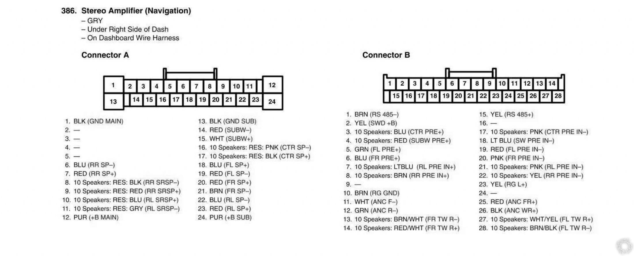
As you can see, the Input connector (Connector B) has 4 pins for front tweeters (13,14,27 and 28). But the output connector (Connector A) has no outputs for the front tweeters. Any thoughts on why this is? I would understand it if the idea is that the Front outputs go to both the front door speakers and the front tweeters, and the front tweeters just have a high-pass crossover on them (which appears to be the case with the factory tweeters), but then, why are there front tweeter inputs at all?
|