Hello all,
Can anyone share wiring diagram for Flashlogic FLRSCH4 plug and play remote starter harness for grand caravan. This remote starter works for grand caravan models 2008 and up. I took this off of my old caravan. I didn't have the tools with me at that time so just cut the wires and thought I would buy a new harness. Unfortunately, that harness [ADS-HRN-(RS)-CHO4 VER 1.11] for FLRSCH4 has been discontinued. Now, the only way is to attach this harness wires manually to the caravan's ignition switch wiring harness. If anyone owns this plug and play remote starter, can you please share the wiring diagram of this harness with labels?
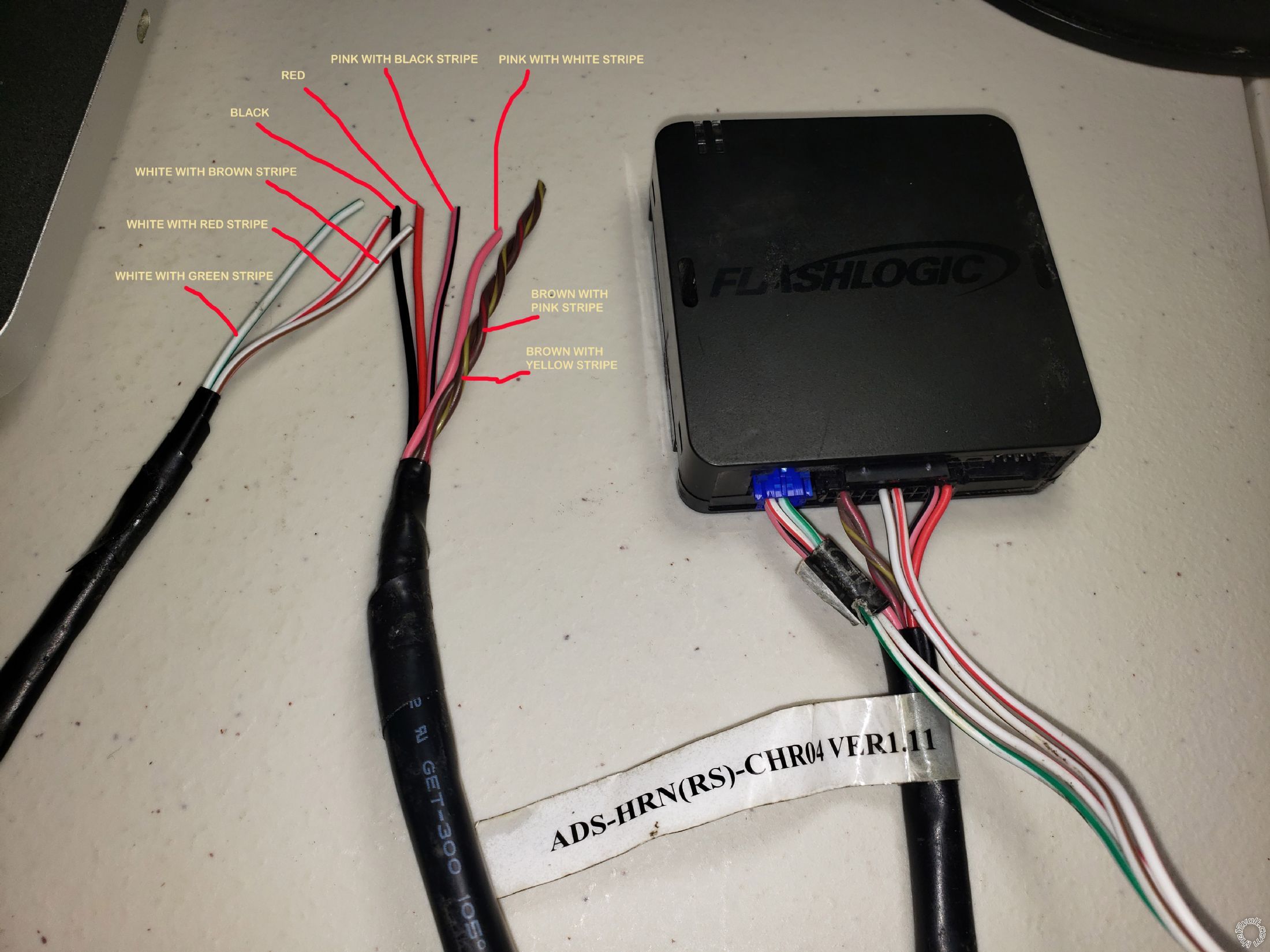
I am trying to install this remote starter to 2015 dodge grand caravan 3.6L.
I have attached A PICTURE OF THE UNIT AND HARNESS WITH COLOUR LABELS below. The bunch with 6 wires (black, red, pink/black, pink/white, brown/pink & brown/yellow) was attached to the caravan's ignition switch. The other bunch with three wires was not connected to anything.
I am looking for:
1. Wiring diagram for Flashlogic FLRSCH4 plug and play remote starter harness [ADS-HRN-(RS)-CHO4 VER 1.11].
2 Wiring diagram of 2015 dodge grand caravan 3.6L ignition switch harness.
Thank you
Jat
Here's what I have for your Grand Caravan.
GRAND CARAVAN 2008-2016
KEY T-HARNESS IMMOBILIZER
CHRKEY4 N/A CHRYSLER'S MULTIPLEX IGNITION/ANTI-THEFT SYSTEM, See NOTE #1
PART COLOR LOCATION DIAGRAM
12 VOLT CONSTANT RED (+) @ BATTERY or TIPM, Note #2
STARTER NOT USED FOR REMOTE STARTING!
STARTER 2 N/A
IGNITION 1 PINK/WHITE (+) @ WIRELESS IGNITION NODE (12-PIN PLUG) PIN 3, Note #3
IGNITION 2 N/A
IGNITION 3 N/A
ACCESSORY/HEATER BLOWER 1 NOT USED FOR REMOTE STARTING!
ACCESSORY/HEATER BLOWER 2 N/A
KEYSENSE N/A
PARKING LIGHTS ( - ) for (-) connection USE HAZARDS, WHITE/ DK. BLUE (-) @ HAZARD SWITCH , BLACK 12 PIN PLUG, PIN 1
PARKING LIGHTS ( + ) WHITE/PURPLE(+) (Right) in DRIVERS KICK PANEL, Harness to Rear of Vehicle.
POWER LOCK PURPLE/DK. GREEN (-) thru a 330 Ohm Resistor (Base Models) in DRIVERS KICK PANEL or TIPM (PLUG(C7) Pin 2, Note #2
POWER UNLOCK Use LOCK wire, (-) thru a 100 Ohm Resistor, Note #4
LOCK MOTOR WIRE TAN/WHITE (+) 5-wire type in DRIVERS KICK PANEL or TIPM (PLUG(C6) Pin 8, Note #2
DOOR TRIGGER PURPLE (-) in DRIVERS KICK PANEL or TIPM (PLUG(C7) Pin 11, Note #2
DOMELIGHT SUPERVISION YELLOW/PURPLE (+) @ PASSENGER A PILLAR or INSTRUMENT CLUSTER(PLUG(C2) PIN 4
TRUNK RELEASE PURPLE/TAN (-) thru a 4700 OHM Resistor (Power Liftgate) @ Power Liftgate Switch or PLM, (22-PIN PLUG) PIN 14, Note #5
SLIDING POWER DOOR N/A
HORN DK. GREEN/PURPLE (-) @ HORN SWITCH or INSTRUMENT CLUSTER(PLUG(C3) PIN 10
TACH Any wire NOT BROWN/WHITE (AC) @ Any FUEL-INJECTOR
WAIT TO START LIGHT N/A
BRAKE WHITE/DK. GREEN (+) @ BRAKE SWITCH or TIPM (PLUG(C7) Pin 10, Note #2
FACTORY ALARM DISARM DISARMS with FACTORY REMOTE ONLY!!
ANTI-THEFT CHRYSLER'S MULTIPLEX IGNITION/ANTI-THEFT SYSTEM, See NOTE #1
NOTES
NOTE #1: This Vehicle is Equipped with CHRYSLERS MULTIPLEX IGNITION/ANTI-THEFT SYSTEM that requires a INTERFACE BYPASS MODULE Part # DBALL2 for REMOTE STARTING and for the KEYLESS ENTRY, when using the Interface Bypass the Resistors for the Door Locks is no longer needed.
Note #2: the TIPM (Totally Integrated Power Modlue) is located in the Engine Compartment, on the Drivers side.
Note #3: the WIRELESS IGNITION NODE is part of the IGNITION Switch.
Note #4: on all other models use the LT. GREEN/WHITE (-) @ the PASSENGER DOOR Lock Switch or the PDM( Passenger door Module) 10 PIN PLUG , PIN 4. The PDM is located in the Passenger Door.
Note #5: the PLM (Power Liftgate Module) is located in the Driver side Rear Quarter Panel.
-------------
 the12volt Support the12volt.com
https://images.idatalink.com/corporate/Content/Manuals/RS-CH4/DIR-CH(RS)-CH4-[FLRSCH4]-EN_20200320.pdf
since you cut off the harness side just use pin number to match the wires, ms2 connection will be the hard part with no real wire colors given or shown
-------------
33 years as a installer now just a retired old guy. Favorite thing to install/topic are remote starts/car alarms. Stop using test lights!!!