Reading 1993 Subaru KS4 Sambar Wiring Diagram
Printed From: the12volt.com
Forum Name: Vehicle Wiring Information & File Requests
Forum Discription: Request Car Alarm, Car Stereo, Cruise Control, Remote Starter, Navigation, Mobile Video, and Other Vehicle Specific Wiring Info, Manuals, Tech Tips
URL: https://www.the12volt.com/installbay/forum_posts.asp?tid=146723
Printed Date: April 08, 2026 at 7:41 AM
Topic: Reading 1993 Subaru KS4 Sambar Wiring Diagram
Posted By: lindylex
Subject: Reading 1993 Subaru KS4 Sambar Wiring Diagram
Date Posted: February 11, 2021 at 1:11 AM
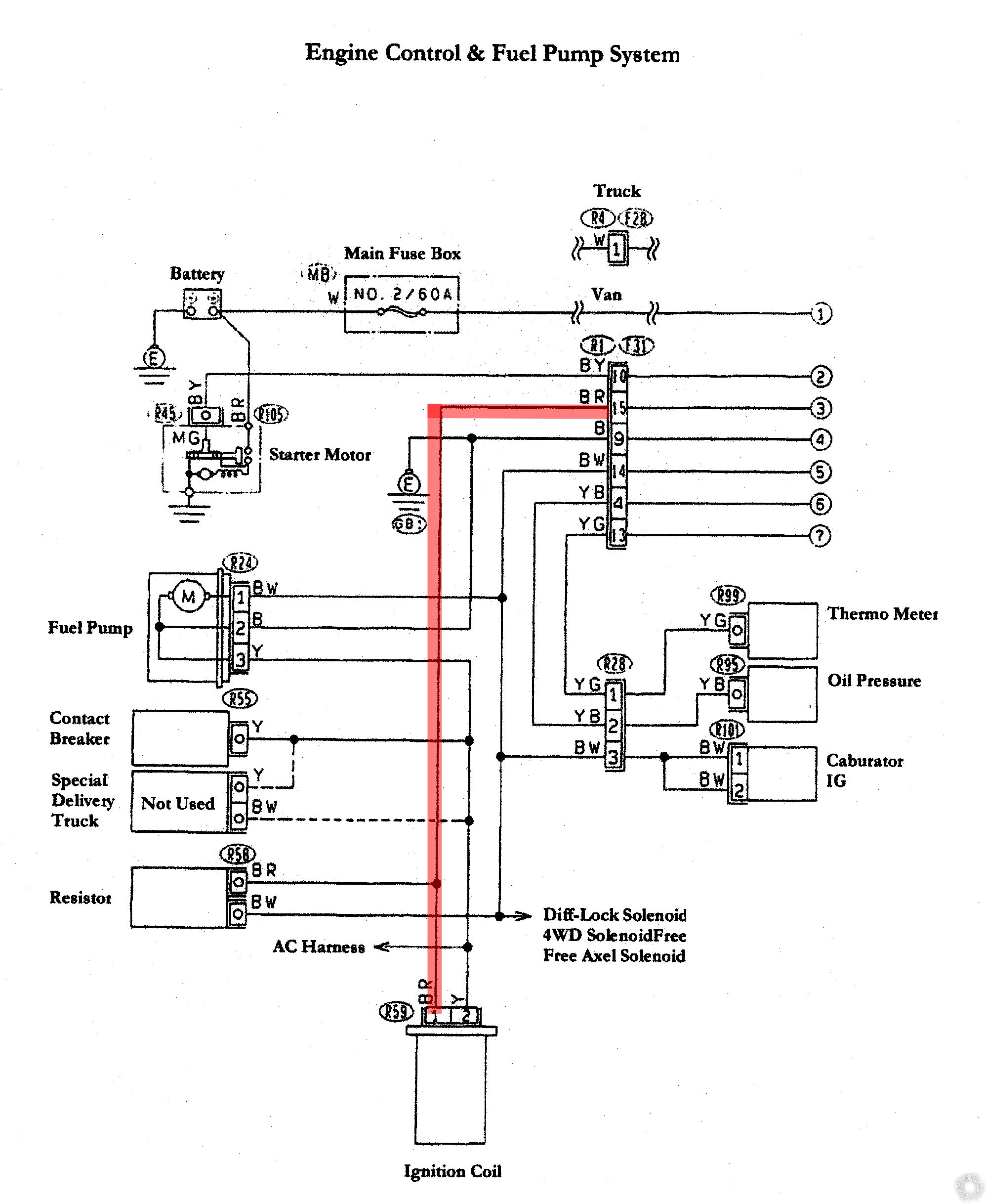
My red overlay of the BR wire connects to an ignition coil that connects to a 15A fuse. I do not see where this gets power from. That is what send power to the 15 A fuse that then send power to the ignition coil.
Replies:
Posted By: i am an idiot
Date Posted: February 11, 2021 at 7:25 AM
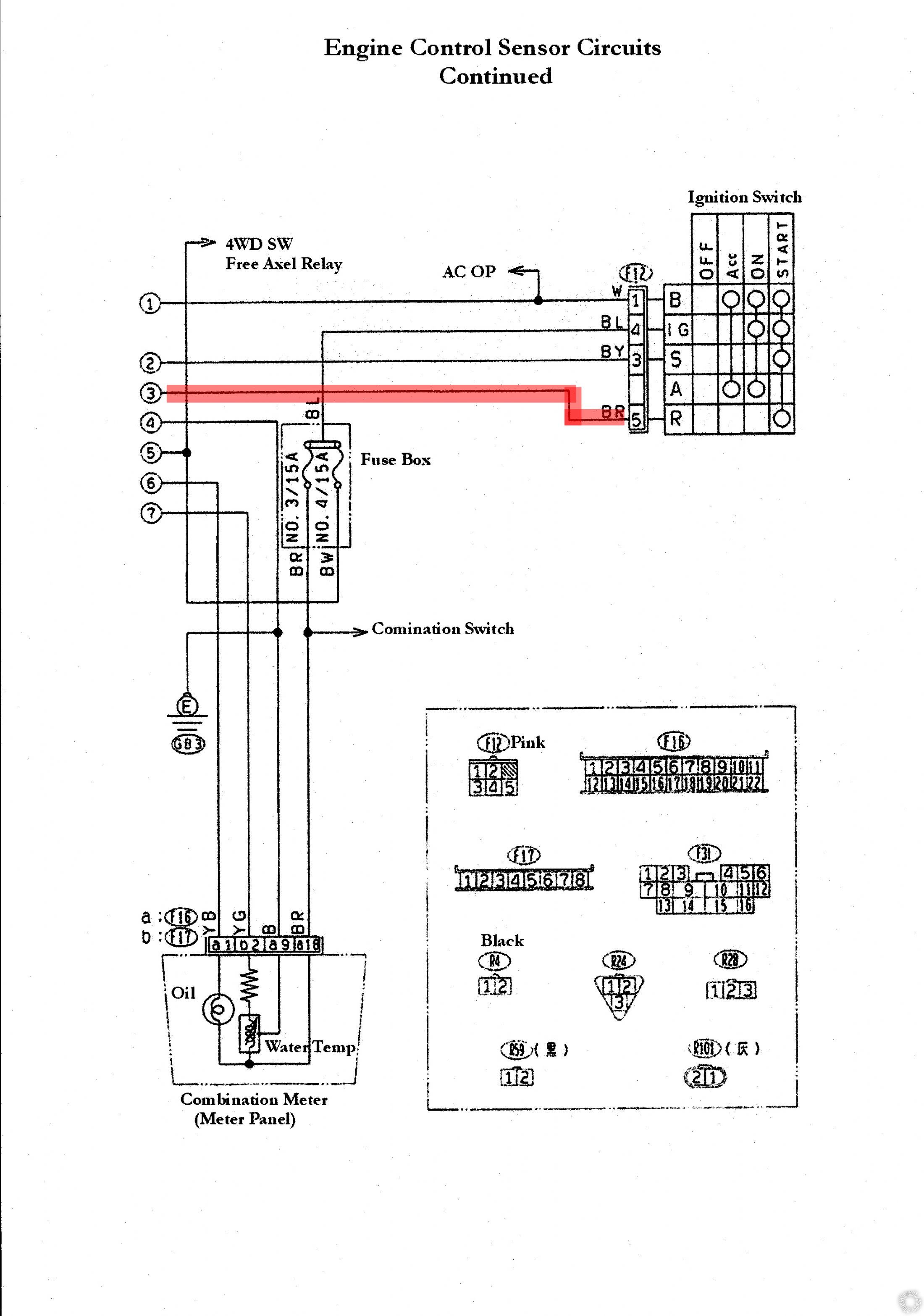
See the numbers 1 2 3 4 5 6 and 7 to the right of where your red line stops? On another page of the diagram you will see those same numbers in that same order, we need that page of the diagram. We need to see where #3 goes.
Posted By: lindylex
Date Posted: February 11, 2021 at 5:38 PM
i am an idiot, thanks for this very simple to you tip but made a big difference for me. "See the numbers 1 2 3 4 5 6 and 7 to the right of where your red line stops? On another page of the diagram you will see those same numbers in that same order..."
I was not sure what those numbers meant.
Let me attempt to explain what I think this is saying. The BR( Black Red ) wire connect to position 5 on the back of the connector attached to the "Ignition Switch". It only receives power when the ignition switch is in the "START" position. I am not sure what provides power to this part of the circuit.
Thanks for the tip.
Posted By: geepherder
Date Posted: February 11, 2021 at 7:21 PM
It's powered through the ignition switch terminal B (battery) via the 60 amp main fuse.
Under "Ignition Switch", the small circles refer to the terminals that are connected when the key is in that position.
-------------
My ex once told me I have a perfect face for radio.
Posted By: i am an idiot
Date Posted: February 11, 2021 at 7:21 PM
Legend of right of your latest picture is as follows.
B = Battery
IG = Ignition
A = Accessory
R as far as I can tell would be for Run.
The way the dots work in that same section is as follows.
Across the top are the words Off Acc On and Start.
When in off there is nothing connected to anything. With key in Acc, notice the battery connection is connected to only the Accessory output. WIth key in on position the battery is now connected to ignition and accessory. In start position notice that everything except the accessory is powered. I really have no idea how this would work with the ignition coil only receiving power when the key is in the start position. I would assume it should be connected to the ignition circuit. If there is not voltage on that wire when attempting to start the vehicle, you may want to use a relay that is triggered by the start wire and make that also power your wire in question.
What is the problem with the vehicle? When you try to start does it even attempt to turn the engine?
Posted By: Ween
Date Posted: February 11, 2021 at 9:51 PM
IG terminal of switch supplies power to the ignition coil through the resistor. The ignition coil would be supplied 9-10 volts typically. When starting, the coil is supplied 12 volts (R terminal), to make starting easier. This is a simple breaker points style ignition system. Running the coil on 12 volts continuously would result in the breaker points contacts arcing excessively and burning up (failing).
Posted By: lindylex
Date Posted: February 11, 2021 at 11:36 PM
i am an idiot wrote:
Legend of right of your latest picture is as follows.
B = Battery
IG = Ignition
A = Accessory
R as far as I can tell would be for Run.
The way the dots work in that same section is as follows.
Across the top are the words Off Acc On and Start.
When in off there is nothing connected to anything. With key in Acc, notice the battery connection is connected to only the Accessory output. WIth key in on position the battery is now connected to ignition and accessory. In start position notice that everything except the accessory is powered. I really have no idea how this would work with the ignition coil only receiving power when the key is in the start position. I would assume it should be connected to the ignition circuit. If there is not voltage on that wire when attempting to start the vehicle, you may want to use a relay that is triggered by the start wire and make that also power your wire in question.
What is the problem with the vehicle? When you try to start does it even attempt to turn the engine?
Thanks for explaining. The B, IG, S, A and R how did you know what those letters meant? I had somewhat of an idea.
This is the situation the car's starter will turn over but I am not getting any power to the ignition coil. The 15A fuse blows every time I turn the key to the "On" and "Start" position. Not sure why the "On" triggers the failure since it should not have power going to it. I need to double check that.
Because it fails I can not get spark.
Thanks
Posted By: lindylex
Date Posted: February 11, 2021 at 11:59 PM
Ween] wrote:
IG terminal of switch supplies power to the ignition coil through the resistor. The ignition coil would be supplied 9-10 volts typically. When starting, the coil is supplied 12 volts (R terminal), to make starting easier. This is a simple breaker points style ignition system. Running the coil on 12 volts continuously would result in the breaker points contacts arcing excessively and burning up (failing).
This makes sense why the fuse blows when the key is in the "ON" position. Power is coming in from the from the battery to the "IG" ignition (4, position and wire BL ).
What I do not understand is how did you decipher the BL wire supplies powers the resistor? I do not recognize the symbol for the resistor being used here if it is.
I see a rectangle with "Fuse Box" labeled next to. This encapsulates BR No. 3/15A and BW NO. 4/15. How would you know this is referring to the resistor?
Following your logic then my issue is that resistor before the ignition coil. I really want to learn how you figured that out.
Thanks
Posted By: i am an idiot
Date Posted: February 12, 2021 at 9:41 AM
The wavy line at the 3/15 and 4/15 is the symbol for a fuse.
Posted By: i am an idiot
Date Posted: February 12, 2021 at 9:48 AM
Can you unplug the free axle solenoid? Bottom right of first pic. Just above and to right of coil. Which fuse is blowing 3/15 or 4/15?
Posted By: lindylex
Date Posted: February 12, 2021 at 11:31 AM
i am an idiot wrote:
Can you unplug the free axle solenoid? Bottom right of first pic. Just above and to right of coil. Which fuse is blowing 3/15 or 4/15?
I can "unplug the free axle solenoid?". Fuse 3/15A is the fuse that keeps on blowing.
Posted By: i am an idiot
Date Posted: February 12, 2021 at 3:59 PM
Can you find another page that tells us where or what the combination switch is? Do not need to unplug the free wheel solenoid. Unplug the water temp gauge and the oil pressure light. Should be the one plug with 4 wires on it.
Posted By: lindylex
Date Posted: February 12, 2021 at 11:55 PM
I made a mistake it was position 4/ 15A. I think this wiring diagram is not correct. It has the wrong color for one of the wires going to the ignition coil. Also there is no resistor immediately next to the ignition coil.
Posted By: i am an idiot
Date Posted: February 13, 2021 at 9:10 AM
Things in the diagram are not placed where they are located physically. Since 4/15 is the one blowing, disconnect the solenoid we mentioned earlier and the plug on the meter and oil light and see if that makes the fuse quit blowing.
Posted By: i am an idiot
Date Posted: February 13, 2021 at 1:12 PM
Everything connected to line 5 is also suspect. Fuel pump, carburetor and the free wheel relay at top of one of the pictures.
Posted By: lindylex
Date Posted: February 13, 2021 at 3:55 PM
[SOLVE SOLUTION]
For anyone following this thread here are the updates. I removed the battery's metal housing to get access to a 30A and 60A fuse. They both were fine. The 60A fuse had signs of overheating. I did a continuity check on both and got zero resistance. I reseated them and put the battery back together.
The wiring diagram I have is not correct. The colors of the wires going to the ignition coil are Yellow and ( Black and White ). This diagram states they are Yellow and ( Black and Red ). This is not correct. The diagram also states that there is a resistor connected to the incorrectly labeled ( Black and Red ) wire. Following the harness if facing the truck and passenger side on the left going to the right, driver side the first things I see are a chassis ground wire that grounds near the ignition coil, second I see a connector going a wire deeper into the engine and third a wire to the distributor. Either way I would like to be wrong and to discovering where. But I see no resistor.
I decided to clean the two chassis ground points in the back by unscrewing them and scrubbing the area with a brass wire brush. I did the same to the chassis ground point by the battery. After this I placed a new 15A fuse in position 3 and placed the ignition in run the voltage was stable and no longer dropping out. The blowing fuses ended.
Then the Subaru Sambar Carburetor Solenoid , SKU: 16196-KA140 at the top on the passenger side of the carburetor caught on fire. It burnt the black ground wire off. I took some of the engine a part to trace that wire. I found that the carburetor solenoid was plugged into the harness with a yellow wire and black wire was ground where the carburetor solenoid attaches to the carburator. I disconnected and tested the engine and now I have spark.
I think if we had the correct giagram things would have been much simpler.
Thanks everyone.
Posted By: pit pros quick
Date Posted: May 21, 2024 at 9:19 AM
I know this is am old thread, but I am new and working on a customers SAmBar. The original problem was random crank, no start. customer insisted that the fuel pump was bad. we put on a new universal low pressure pump and connected the black and the yellow wires together for the ground and the blk/wht wire to positive. now we have plenty of fuel and no spark. 2 distributors later, still no pulse on the coil. I found this diagram and also found another forum about this issue. using this info, I cut the black wire to the pump and it started immediately and seems to run fine. My question is, should I ground this wire to chassis or leave it alone? It looks like it is the ground for many other things on the circuit and is grounded twice to the chassis. Also, long term, what could be any problems with it detached from the original harness since the fuel pump is not original? If there is no problems foreseen, I will put this sambar back together and roll it. Thanks.
-------------
c. c.
|