2001 jimmy remote start/alarm
Printed From: the12volt.com
Forum Name: Vehicle Wiring Information & File Requests
Forum Discription: Request Car Alarm, Car Stereo, Cruise Control, Remote Starter, Navigation, Mobile Video, and Other Vehicle Specific Wiring Info, Manuals, Tech Tips
URL: https://www.the12volt.com/installbay/forum_posts.asp?tid=40490
Printed Date: April 20, 2026 at 1:40 AM
Topic: 2001 jimmy remote start/alarm
Posted By: pancoaster
Subject: 2001 jimmy remote start/alarm
Date Posted: October 07, 2004 at 10:07 PM
Im trying to install a remotestart/arlarm in my s-10 2001 Jimmy. I have searched the forums and found this so far: 3pin doorlock:
1 blue negative unlock- 500mA Tan-Left Steering Column
2 red (n/a) +500mA for plugin relay -
3 green negative lock- 500mA Gray-Left Steering Column 6pin starter:
1 red 12V+ Red-Ignition Switch Harness
2 red (n/a) 12V backup+ -
3 brown (n/a) 2nd ignition output+ ?
4 orange accessory output+ Orange-Ignition Switch Harness
5 yellow Ignition output+ Pink-Ignition Switch Harness
6 violet starter output+ Yellow-Ignition Switch Harness 20pin main harness:
1 grn/wht Brake Input+ White-Brake Switch
2 blk/gry (n/a) tach input -
3 wht/red (n/a) aux 2 output- 500 mA -
4 blk/wht dome light output- 500 mA Yellow-Light Switch
5 yellow Ignition input- ?
6 blue/yel (n/a) parking break input -
7 blu/wht Passenger unlock output- 500mA Tan-Left Steering Column
8 blu/org (n/a) ground when running ?
9 blk ground- ground
10 red 12v+ Red-Ignition Switch Harness
11 violet positive door input+ ?
12 green negative door input- White (-) Courtesy Light/BCM Front of Console
13 wht/blk (n/a)negative hood input- -(works with dome lights)
14 orange armed output- 500mA ?
15 vlt/wht factory disarm output- 500mA ?
16 wht/vlt factory rearm output- 500mA ?
17 brown Siren output+ Red-Siren wire
18 grey (n/a) aux 1 output- 500mA -
19 white Parking light relay Light Blue (+) Light Switch
20 brn/wht Horn output- 500mA Black Steering Column Is this acurate knowledge? I also have a few questions:
Do i need to connect the 2nd ignition output?
Where should i connect the Ignition input?
Will i use the ground when running wire?
Do i need the positive door input wire? Are there any factory alarms systems i have to worry about?
Should i connect the armed output, factory disarm, and factory rearm wires?
Replies:
Posted By: mo12v
Date Posted: October 08, 2004 at 10:03 AM
That is for your Alarm?????
Do U need wiring for Vehicle?
<<<<<<Do i need to connect the 2nd ignition output?>>>>
YES
<<<<<<Where should i connect the Ignition input?>>>>>>
Ignition Switch
<<<<<<Will i use the ground when running wire?>>>>>>>
YES for PassLock
<<<<<<<Do i need the positive door input wire?>>>>>>>
NO | Constant 12 volts | RED (2) | IGNITION SWITCH HARNESS | | Ignition 12 volts | PINK | IGNITION SWITCH HARNESS | | Starter | YELLOW | IGNITION SWITCH HARNESS | | Dome Light | WHITE (-) | AT COURTESY LIGHT ABOVE THE DASH * | | Trunk Pin Switch | DOME LIGHT | AT COURTESY LIGHT ABOVE THE DASH | | Parking Lamp | L BLUE (+) | AT LIGHT SWITCH HARNESS | | Power Lock | L BLUE (+) | AT MODULE ABOVE DRIVER KICK PANEL | | Power Unlock | WHITE (+) | AT MODULE ABOVE DRIVER KICK PANEL |
* At The BCM Located Behind The Driver's Dash In Front Of The Center Console, Tan Covers Driver's Doors,Orange Covers Passenger's Door,Blue/White Covers Rear Doors, And Pink/Black Covers The Hatch.Diode Isolation Needed Cathode (Band) Side Of Diode Faces OEM Wires. Positive Pulse Door Locks | Accessories | | Window Up | D\ D BLUE P\ L BLUE D\ D GREEN P\ L GREEN @ MAIN SWITCH | | | Window Down | F/ BROWN F/ TAN R/ VIOLET R/ VIOLET | | | Ign Key Warn | L GREEN (-) | STEERING COLUMN HARNESS | | Trunk Release | BLACK (-) | AT RELEASE SWITCH IN DASH | | OEM Horn | BLACK (-) | STEERING COLUMN HARNESS | | Headlights | WHITE (+) | AT LIGHT SWITCH HARNESS (+) | | OEM Alarm Arm | TAN (-) | AT BODY CONTROL MODULE IN FRONT OF | | OEM Alarm Disarm | L GREEN (-) | CENTER CONSOLE |
Reversal Rest At Ground Power Window Circuit | Remote Start | | Tach Signal | WHITE | AT IGNITION CONTROL MODULE * | | Ignition #2 | WHITE | IGNITION SWITCH HARNESS | | Ignition #3 | ORANGE | IGNITION SWITCH HARNESS | | Accessory | WHITE | IGNITION SWITCH HARNESS | | Neutral Safety | NOT GROUNDING TYPE - | OEM SWITCH OPENS STARTER CIRCUIT | | Brake Light | WHITE (+) | AT SWITCH ABOVE BRAKE PEDAL | | Reverse Light | L GREEN (+) | AT UNDER HOOD FUSE BOX | | Rear Window Defrost | N/A | TIMER BUILT INTO SWITCH |
* Ignition Control Module Is Located On The Passenger Side Of The Engine Compartment. Wire Can Also Be Found As WHITE At Inst Cluster Or PCM On Passenger Side Of Engine Copmartment. G.M. PASSLOCK II Diagram. ------------- MO
Don't Learn from Others Mistakes
You Might Be the One That Knows.
Posted By: pancoaster
Date Posted: October 08, 2004 at 11:38 AM
Posted By: pancoaster
Date Posted: October 08, 2004 at 2:54 PM
i have two more questions concerning a couple wires. ground when running (-) 500mA: ?
Connect to an optional factory security bypass module if needed. armed output- 500mA: ?
Provides a ground output while armed to activate a relay for starter defeat and anti-grind protection. should i use these wires from my unit? also, the unit i bought only has first and second ignition output wires. what should i connect to the third ignition wire?
Posted By: mo12v
Date Posted: October 08, 2004 at 4:52 PM
<<<<<ground when running (-) 500mA: ?
Connect to an optional factory security bypass module if needed.>>>>>
Connect to the PASSLock unit for this vehicle <<<<<armed output- 500mA: ?
Provides a ground output while armed to activate a relay for starter defeat and anti-grind protection.>>>>>>
Goes to Relay for Starter Kill ( U don't really need it ) should i use these wires from my unit? <<<<also, the unit i bought only has first and second ignition output wires. what should i connect to the third ignition wire?>>>>>
U will need a SPDT Relay to hook to your Remote Start and 3rd Ignition wire.
( If U R not sure on how to install, U probably shoul seek professional help ) Serious damage may result ------------- MO
Don't Learn from Others Mistakes
You Might Be the One That Knows.
Posted By: pancoaster
Date Posted: October 09, 2004 at 5:58 PM
is this the correct diagram for making a 3rd ignition wire: 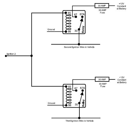
Posted By: pancoaster
Date Posted: October 09, 2004 at 6:03 PM
image wont work, typing it: 2nd ignition wire to (85) on two separate relays. 12v to (87) on each relay. ground to (86) on both relays. 2nd ignition wire to (30) on one relay. 3rd ignition wire to (30) on other relay.
Posted By: mo12v
Date Posted: October 09, 2004 at 8:50 PM
If U don't have an Extra - Output from your Module, that will work.
Make sure U use 12 Guage wire on Pin 30 & Pin 87
-------------
MO
Don't Learn from Others Mistakes
You Might Be the One That Knows.
|