simple diy video/audio switch
Printed From: the12volt.com
Forum Name: Mobile Video, GPS, and Navigation
Forum Discription: Mobile Video Head Units, DVD Players, LCD and TFT Monitors, Navigation, GPS, PS2, PS3, XBox, etc.
URL: https://www.the12volt.com/installbay/forum_posts.asp?tid=123406
Printed Date: March 22, 2026 at 11:24 AM
Topic: simple diy video/audio switch
Posted By: pneffkell
Subject: simple diy video/audio switch
Date Posted: September 07, 2010 at 6:41 PM
I did a search and found a brief mention of using relays and diodes as a a/v switch
I am new to all of this so I need a drawing of how to build a simple audio video switch.
I have two monitors and two sources - a dvd player and sirius backseat tv. I want a manual switch for each monitor that switched between the two sources. Yes I know they make cheap remote controlled units. I already will have two remotes. 1 for the backseat tv and 1 for the dvd. I don't want to add more.
Someone help would be appreciated. Plus I would even pay someone to build this for me.
Thanks
Replies:
Posted By: afdanw
Date Posted: October 16, 2010 at 12:24 PM
Hey, i have a diagram of how to make a vid switch with just relays on my home computer. I am at work right now, but send me a Private message and remind me to send you te diagram. When i get home, check my e-mail, and get your reminder; i will send you the diagram. I have never used the relay video switcher, so i cannot say for sure how well it works, but there is no reason it should not be good. For your set up you would have to make 2 of them, one for each screen. Also you would have to duplicate it again for audio switching. My diagram is 4 relays per switch. If you want to swith the audio with the video, and you want the screens to watch seperate video/audio sources, will need a total fo 16 relays.
-------------
If your cousin is such a good installer, and he will install anything for a 6 pack; why are you talking to me?
Posted By: i am an idiot
Date Posted: October 17, 2010 at 5:10 AM
3 relays, one for left audio, one for right audio, and one for video. Wire each of the 3 relays as follows: Output to terminal 30, primary source to terminal 87A, secondary source to terminal 87.
Ground to terminal 85 of all 3 relays. Connect a switched power source through a control switch to terminal 86 of each of the relays.
Solder a diode across terminals 85 and 86 of one of the relays. Banded end to 86
Posted By: afdanw
Date Posted: October 17, 2010 at 1:05 PM
A few question about your desing.
1. Should your signal sources be twin lead/coax/RCA? if so are you only using one part of the wire? If you can do that, i would assume you use the positive side/ center connector.
2. What is the point of that diod. what is it acomplishing, and if you were to take it out, what would go wrong?
If your way works, it sounds much easier than mine, but for argument sake, i am still going to post my design here. 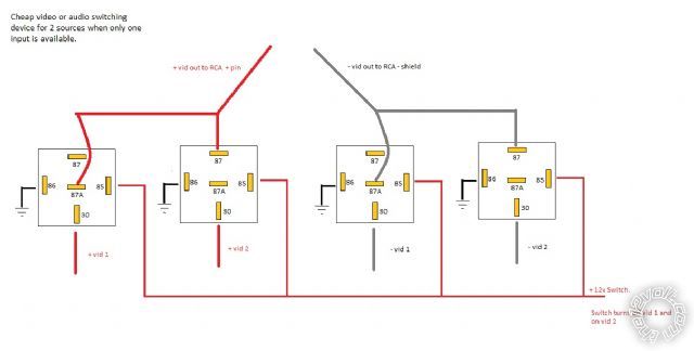
------------- If your cousin is such a good installer, and he will install anything for a 6 pack; why are you talking to me?
Posted By: i am an idiot
Date Posted: October 17, 2010 at 2:33 PM
Yours will work too, but it will take 6 relays where mine will need only 3. Yes the center conductor is what needs to be switched. Strip all cables back far enough to expose enough center conductor to work with. Twist and solder all shield connections together.
The diode is there to eliminate the terrible audible pop that you will hear everytime you switch the relays off.
Posted By: i am an idiot
Date Posted: October 17, 2010 at 4:35 PM
The relays you drew are Single Pole Double Throw design. There is a common terminal (30), a normally closed terminal (87a) and a normally open terminal(87). At rest, terminal 87a is connected to terminal 30. When the relay is energized, terminal 87 is now connected to terminal 30. Terminal 30 is the output, and the state of the coil determines which of the 2 inputs will get to that terminal.
Posted By: afdanw
Date Posted: October 18, 2010 at 12:35 PM
i am an idiot wrote:
The relays you drew are Single Pole Double Throw design. There is a common terminal (30), a normally closed terminal (87a) and a normally open terminal(87). At rest, terminal 87a is connected to terminal 30. When the relay is energized, terminal 87 is now connected to terminal 30. Terminal 30 is the output, and the state of the coil determines which of the 2 inputs will get to that terminal.
Yes, kind of. when i made it i was meaning for 30 to be the input an 87 to be the output, but that is kind of irelivant. One thing i never thought about was using 87a as an input, with 30 as its output. i have alwais used 87a as an output. your idea is smart, and it should have been obvious to me, but somehow i did not think about it. Also thank you for the heads up on not even needing to switch the shieldings on the signal wires, and only needing to switch the positive pins. I dont know y i didnt think of that either. i know that video signal travles as a modulated sign wave, but i just wasnt thinking about the fact. ------------- If your cousin is such a good installer, and he will install anything for a 6 pack; why are you talking to me?
|