overhead flip down monitor
Printed From: the12volt.com
Forum Name: Mobile Video, GPS, and Navigation
Forum Discription: Mobile Video Head Units, DVD Players, LCD and TFT Monitors, Navigation, GPS, PS2, PS3, XBox, etc.
URL: https://www.the12volt.com/installbay/forum_posts.asp?tid=133637
Printed Date: March 22, 2026 at 12:54 AM
Topic: overhead flip down monitor
Posted By: fosgate24360
Subject: overhead flip down monitor
Date Posted: February 20, 2013 at 12:14 AM
hey all, thinking of getting a new motorized flip down monitor. was wondering if there would be a way to wire in a switch/relays in the power line of it and mount the switch up at the dash so i could just flip the switch and the monitor would open/close instead of always pressing the power/open button on the unit itself? thx in advance to anyone who replies.
Replies:
Posted By: fosgate24360
Date Posted: February 21, 2013 at 9:57 PM
anyone?
Posted By: fosgate24360
Date Posted: February 22, 2013 at 11:20 PM
^
Posted By: oldspark
Date Posted: February 23, 2013 at 5:59 AM
Probably.
It sounds like you merely need to extend the unit's on-off switch.
Posted By: fosgate24360
Date Posted: February 23, 2013 at 7:30 AM
thx for the reply. thats what i was thinking also. the unit comes on either by inserting a disc or the power button. so i was thinking if i put the power line on a relay, id still have to hit the power button on the unit or insert a dvd correct?
Posted By: oldspark
Date Posted: February 23, 2013 at 9:01 AM
If the power switch is a mere momentary push button, then add a separate switch and join its 2 wires across the original switch. Hence press either to turn on or off.
If it's a latching switch, it gets more complicated.
Posted By: fosgate24360
Date Posted: February 23, 2013 at 9:18 AM
yea its a momentary switch..no latch on it. will i be able to just wire in the switch with the existing power wire coming out from the unit or will i need to actually take the unit apart and solder in new power leads and extend it from the unit to the new switch on the dash?
Posted By: oldspark
Date Posted: February 23, 2013 at 4:31 PM
No need to pull power. But yes, you'll have to pull the unit apart - and probably solder as well - at your own risk.
All you need do is "parallel" the existing switch. That means finding the 2 solder spots where the switch connects to the internal PCB etc. I do NOT suggest dismantling the switch to substitute the 2 added wires.
This all assumes a plain momentary on single contact (2 terminal) switch. There are other switch possibilities...
Your equivalent added switch with its 2 wires is connected across the existing switch terminals or wires, ie:
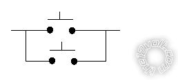
Hence you can push either (or both) and it simply mimics how the original switch behaves.
There is no need to involve the unit's power since the unit's circuitry handles that.
Nor is there any need for relays - unless as a solution for very long extended wires and interference etc. Depending on the circuitry, it's possible that the new extended wires cause problems (by injecting noise) but that should be solved with a small capacitor (0.01uF etc), but that can be added later only if needed.
You'll need to solder the new wires to the abovementioned solder points. That has an element of risk - not only the usual thermal & solder damage etc, but also electrical damage to sensitive components thru static etc depending on the circuit. That can be minimised by following normal static handling procedures - ie, grounded soldering iron and unit etc. And (obviously?) with the unit unpowered and disconnected from the vehicle etc.
Actually, I'd suggest extending via a plug and socket for easy removal. Maybe a small 2.5mm or 3.5mm panel socket somewhere on the unit's enclosure, and your switch to the suitable plug?
Posted By: fosgate24360
Date Posted: February 24, 2013 at 10:37 AM
ok thanks for all your info, great apreciated. while we're on the subject, any thoughts as to how to many a standard 7" headrest monitor have direct power(come on/off with ignition)? wanted a work around as oposed to needing to press the power button on them everytime.
Posted By: oldspark
Date Posted: February 24, 2013 at 4:56 PM
No idea, but I expect none.
Some may have the option of a remote like amplifiers that could be connected to IGN though probably ACC is best so they are not on whilst cranking. But then I'd suggest a delay timer so they don't turn on until after the vehicles is started. (The alternator charge light circuit could be used instead, but then they are off when the engine in not running, though there are various ways to keep them on etc.)
But with your extended on switch, something could be rigged up.
Thought has to be given if you want them on with ACC, or be able to turn them off at any time.
I have my HU powered directly off the battery (both for cleanest power and IgSwitch independence) though at the moment the IGN needs to be on to turn it on, but then it stays on until I manually turn it off. (I have yet to fit an "on any time" switch, and maybe one that turns it off when the IGN if off.)
Posted By: fosgate24360
Date Posted: September 08, 2013 at 9:09 AM
well back to my old post here.....i have opened up the overhead motorized monitor to attempt this soldering of the wires for the extended push button. i ended up burning/shorting something out. the unit would still power on as usual but the screen would not open or close(motorized part) and all the buttons would do is light up and have a slight flicker. thank goodness for warranty as i sent it back. a new one(same unit) is on the way and i hope to achieve this with the new. if i post pics of the inside circuits could it make it easier as to what im looking for? thx oldspark
Posted By: oldspark
Date Posted: September 08, 2013 at 5:18 PM
You are very lucky. Warranties do not cover that sorry of damage.
(Hence "at your own risk" in my earlier reply.)
Posted By: fosgate24360
Date Posted: September 13, 2013 at 12:14 AM
yea thank goodness for square trade.....ill try and upload pics of the boards i see inside the unit. hope it helps shed some light on my part
.jpg)
.jpg)
i dont think the white board will have anything to do with wiring in the switch but uploaded it just in case. the white board has the push buttons mounted on it then it connects to the green board(the wires you see in both pics connect both pieces). there are also 2 wires (looks to be a red and a black)under the green board going to the motor which may not have to do with either.....thx again oldspark
Posted By: fosgate24360
Date Posted: September 13, 2013 at 11:50 PM
i did just notice that the unit has some sort of latching switch which is visible when the screen is open/on......if i push it in, the monitor closes and the unit shuts off
|