Hi all,
I had to re-register to log on... My previous ID/password didn't work...
On some 1952 Chevrolet pickups that didn't come with a radio, there was a "Radio Delete Plate" (RDP) installed at the factory to block the hole at the center of the dash. I want to mechanize that radio delete plate to open a rear view camera screen as soon as the transmission (automatic) is put into reverse AND close again after the transmission is put into drive or park (in other words, out of reverse).
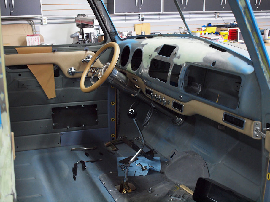
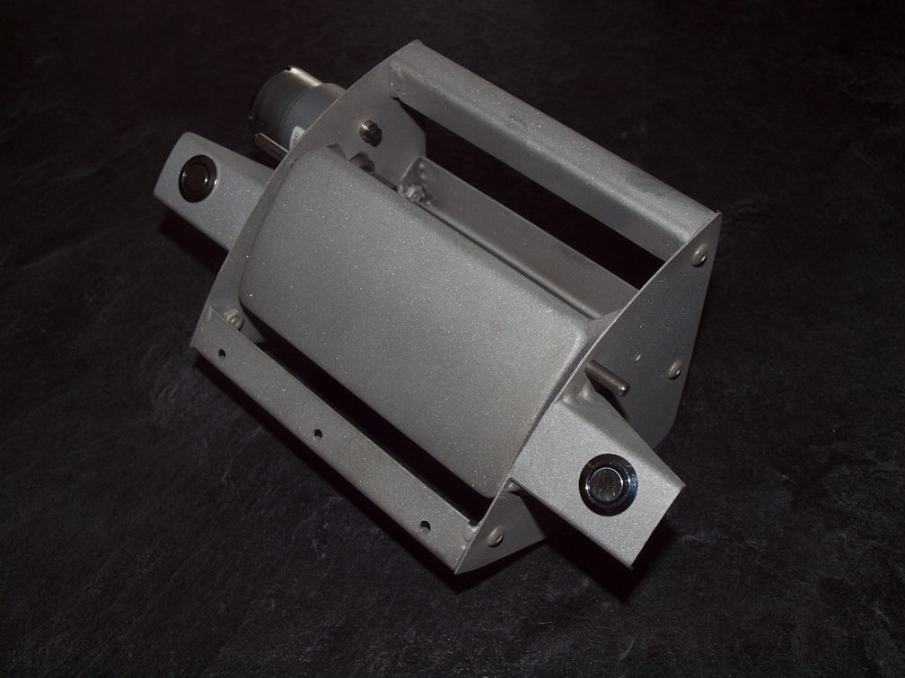
I have fabricated the mechanism to operate the camera screen door using the RDP...
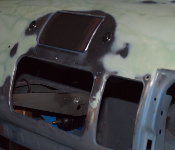
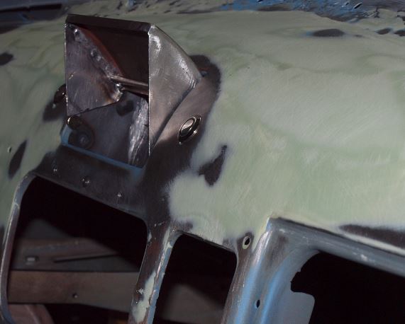
... and it fits under the dash and opens the Radio Delete Plate to show the 4.3" rear view camera screen.
What I DESPERATELY need is a schematic to make it work automatically...
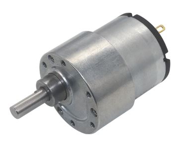
- The motor to open the door is 12 volt.
- The motor is reversible
- The signal to open the camera screen will come from the back up lights (tranny in reverse)
- The signal to close the RDP once the tranny is removed from reverse gear.
What do I need to stop the travel of the RDP opening? A relay, a micro switch?
What to I need to reverse the process and close the RDP once the transmission is out of reverse? Some sort of polarity switch, another relay and another micro switch to stop it's downward travel?
You can email me directly if you need more information...
Any help would be GREATLY appreciated.
52-Chebby
Hi eGuru,
Yes, it's a gear motor... 0.8 amp under load... 8.5 rpm under load (see image below)
What I need is something exactly like an automatic power antenna schematic... Radio On = Antenna goes up and stays up... Until Radio Off = Antenna goes down and stays down until radio is turned on again.
As for your other suggestion, I have access to a Power Window roll-down switch combined with a One-Touch up or down... Using one of these would open the camera door and stop it at the open position but using these would still require a second trigger to close the camera door... That's what I haven't figured out yet.
Thanks
Skylark-53
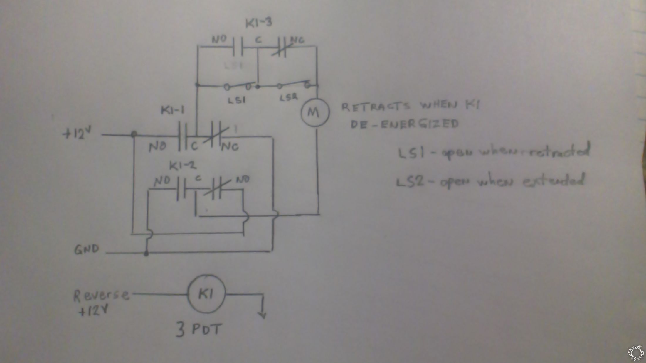
LS1, LS2 - are NC switches which become open reaching the retracted and extended positions (respectively);
M - is your gear motor - connected so that it rotates towards retracted when K1 coil is not energized by reverse 12V;
K1 - is a 3PDT relay (or 2 DPDT relays if easier to source);
Check out my logic on this.
When retracted, LS1 and K1-3 NO contacts are open so motor is not powered.
When reverse energizes coil of K1, K1-3 NO contacts close and bypass LS1. Motor rotates towards extended position until LS2 is activated (opened). Motor stops.
When reverse 12V drops off, K1-3 NC contacts close to bypass the open LS2 switch. Motor rotates towards retracted position until LS1 is activated (opened). Motor stops.