power connector pinout question
Printed From: the12volt.com
Forum Name: Mobile Video, GPS, and Navigation
Forum Discription: Mobile Video Head Units, DVD Players, LCD and TFT Monitors, Navigation, GPS, PS2, PS3, XBox, etc.
URL: https://www.the12volt.com/installbay/forum_posts.asp?tid=42228
Printed Date: May 12, 2026 at 1:59 PM
Topic: power connector pinout question
Posted By: mopwr
Subject: power connector pinout question
Date Posted: November 04, 2004 at 11:56 AM
I bought a Rosen R5000 12V VCR that came without the power cable. Rosen tech support would only give me the part number (VCP Power Cable 15' (Black) - 6015-1013-000) which costs more than I paid for the vcr. Does anyone have one of these that could tell me where the black, red and blue cable go. Thanks in advance,
Darren
Replies:
Posted By: audiopro111
Date Posted: November 06, 2004 at 8:27 PM
open it and look at the board right where the plug should go most electronic boards have abbreviations to what goes where just pay attention while u take it apart so that u can put it back together........oh yeah one more thing go to radio shack and buy u'r self a static band they cost about 2 bucks this is to avoid static to certain components on vcr as they may be samaged due to static..............................Later,
-------------
AudioPro111
Posted By: mopwr
Date Posted: November 07, 2004 at 7:43 AM
I tried that one already. I am a computer technician so I had the screwdriver out as soon as there wasn't a pinout in the owners manual. The connection is a standard 4 pin molex (Like in a power supply for a Pentium 4 computer). 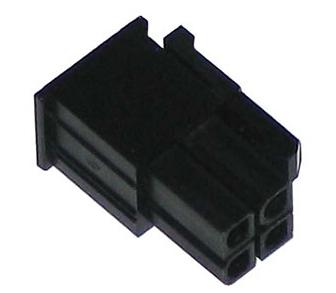
The back of the vcr looks exactly like this clarion 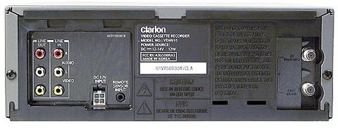 Thanks for the suggestion though, I am open to them all.
Darren
Posted By: audiopro111
Date Posted: November 07, 2004 at 7:38 PM
sorry dude i thought that would do the trick.
-------------
AudioPro111
Posted By: dxav
Date Posted: November 08, 2004 at 9:28 AM
If it takes DC V from the get go, open it back up. Many 12V-18VDC have 4 pin plugs (the PS2 does, in fact).
There are really only 2 things they could be. +V, and GND. You can probably find the ground with a DMM quite easy. Look for a large patch of copper on either side of the PCB.
Also, do a continuity test to match those pins (2 should be connected, and the other 2 connected together, but not connected to the first pair).
If you can't find a ground patch, check the parts, look for a regulator with a part number you can check for online. Then you can be sure it is ground.
The other 2 pins of that connector should be the +V.
Good luck, any questions, let us know. I did the same thing when I converted a PS2 to 12VDC, so I know you can do it.
DXAV
|