power distribution
Printed From: the12volt.comForum Name: General Discussion
Forum Discription: General Mobile Electronics Questions and Answers
URL: https://www.the12volt.com/installbay/forum_posts.asp?tid=135610
Printed Date: April 27, 2024 at 4:56 PM
Topic: power distribution
Posted By: ronemca
Subject: power distribution
Date Posted: December 24, 2013 at 2:52 PM
What I would therefore like is a small box -- preferably without fuses -- to which I can supply ONE power lead...and FROM WHICH I can supply five or six devices.
I know there are replacement battery terminals that allow this, and I also know there are multi-fused terminal blocks...AND non-fused terminal blocks. But I already have inline fuses for my two existing feeds (and yeah - I could re-config those, but I'd rather not) And of course the non-fused blocks require as many inputs as there are active outputs (so that kills the one-in-many-out premise)
I have found a red plastic block that has about eight screws around the base and a 5/16" screw sticking out the top (it looks like a crown; all of the connections are completely exposed). I guess it would do the job...but it's a bit ghetto for my taste.
My connections are about 14g or 16g (as opposed to 4g or 0g) so I don't want or need to replace the POS battery terminal. But aside from that, are there any other options? And/or some online sources that I could visit for ideas (and perhaps product)?
Many thanks, and Merry Christmas!
Replies:
Posted By: Ween
Date Posted: December 24, 2013 at 6:41 PM
you have a power feed input for six circuits.
total current required as well as for each branch?
this will be for the sizing of the input stud as well as wiring in the unit.
control signals are positive or negative? or both?
this is for the number of input/output terminals needed.
a die cast aluminum box to mount six relays inside, these boxes can be bought with mounting flanges. terminal strip along long edge for input/output connections.
power feed through on box as well for well power input.
mark
Posted By: ronemca
Date Posted: December 24, 2013 at 11:53 PM
Ween] wrote:I haven't added it up. At this point I have the two relays mounted and the circuits are working perfectly. In theory I didn't need the relays, because the wireless control boxes are rated at 15A...which I believe is quite enough headroom for what I'm running.
hi,total current required as well as for each branch?
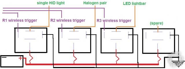
On circuit #1 (R1) I have a single 7" HID light.
On circuit #2 (R2) I have a pair of 4" Halogen lights.
On circuit #3(R3) -- which does not yet exist -- it's going to be a 20" LED lightbar which contains 40 LED's (infinitesimal draw).
But I was a little apprehensive about the wireless control boxes. Clearly the "switch" circuitry is integrated onto a fairly small board inside the box, and I didn't want to take any chances of frying those skinny strips of copper and/or diodes or whatever is inside there. Hence the relays.
Ween]c wrote:Positive; the remote trigger for each relay is provided by the activation of the wireless remote keyfob inside the vehicle.
ntrol signals are positive or negative?
Ween]a wrote:Not entirely sure what you mean here. Are you suggesting a small aluminum box? Sortof 2" x 4" x 8"? And it has flanges inside? May I please see an example?
die cast aluminum box to mount six relays inside, these boxes can be bought with mounting flanges. terminal strip along long edge for input/output connections.
Ween]p wrote:Completely stumped here. (Sorry) I believe we are talking about an aluminum box, inside of which are...let's say...four relays (one for future expansion). One "main" power wire enters the box from the battery, and (inside the box) feeds a bus bar of sorts(?) And from the bus bar four separate leads branch out to each of the four relays. Meanwhile, I have to also bring three separate trigger wires into the box, and...
wer feed through on box as well for well power input.
mark
bring out[/] of the box:
three separate power wires (one to each of the three lighting systems), and one common ground.
This sounds like alotta work for questionable gain. But I want to be sure I am understanding; I realize I have made several assumptions, and maybe I am over-thinking it!
I would also be very pleased to see the terminal bar you're talking about.
Thank you VERY kindly for replying! This will not happen tomorrow or anything...but I am eager to begin the collecting of components (and learning the answers to some of my questions!)
Merry Christmas!
Posted By: ronemca
Date Posted: December 24, 2013 at 11:56 PM
Ween] wrote:I haven't added it up. At this point I have the two relays mounted and the circuits are working perfectly. In theory I didn't need the relays, because the wireless control boxes are rated at 15A...which I believe is quite enough headroom for what I'm running.
hi, <snip> total current required as well as for each branch?
On circuit #1 (R1) I have a single 7" HID light.
On circuit #2 (R2) I have a pair of 4" Halogen lights.
On circuit #3(R3) -- which does not yet exist -- it's going to be a 20" LED lightbar which contains 40 LED's (infinitesimal draw).
But I was a little apprehensive about the wireless control boxes. Clearly the "switch" circuitry is integrated onto a fairly small board inside the box, and I didn't want to take any chances of frying those skinny strips of copper and/or diodes or whatever is inside there. Hence the relays.
Ween]c wrote:Positive; the remote trigger for each relay is provided by the activation of the wireless remote keyfob inside the vehicle.
ntrol signals are positive or negative?
Ween]a wrote:Not entirely sure what you mean here. Are you suggesting a small aluminum box? Sortof 2" x 4" x 8"? And it has flanges inside? May I please see an example?
die cast aluminum box to mount six relays inside, these boxes can be bought with mounting flanges. terminal strip along long edge for input/output connections.
Ween]p wrote:Completely stumped here. (Sorry) I believe we are talking about an aluminum box, inside of which are...let's say...four relays (one for future expansion). One "main" power wire enters the box from the battery, and (inside the box) feeds a bus bar of sorts(?) And from the bus bar four separate leads branch out to each of the four relays. Meanwhile, I have to also bring three separate trigger wires into the box, and...
wer feed through on box as well for well power input.
mark
bring out of the box:
three separate power wires (one to each of the three lighting systems), and one common ground.
This sounds like alotta work for questionable gain. But I want to be sure I am understanding; I realize I have made several assumptions, and maybe I am over-thinking it!
I would also be very pleased to see the terminal bar you're talking about.
Thank you VERY kindly for replying! This will not happen tomorrow or anything...but I am eager to begin the collecting of components (and learning the answers to some of my questions!)
Merry Christmas!
Posted By: ronemca
Date Posted: December 25, 2013 at 12:21 AM
Like this?
Where's a good source for these at a decent price? (assuming this is indeed what you were suggesting!)
Posted By: ronemca
Date Posted: December 25, 2013 at 11:28 AM
In the grand scheme of things, I believe this is what I should have done in the first place...rather than mounting and wiring each relay separately.
And I am also now thinking that it makes more sense to use a 5- or 6- terminal FUSE HOLDER/terminal block in the box, because it will:
a) reduce complexity
b) reduce wiring outside the box
c) be easier to find than a one-becomes-many terminal block...which would still require separate fuses anyway
However...
Aside from soldering (or the dreaded vampire clips - which I heartily dislike) I'm still not sure how to split ONE 8g or 10g power feeder into FOUR separate/smaller branches inside the box. I will have another look at the 5- or 6- fuse terminal blocks; perhaps one of those offers a one-in-many-out option.
Posted By: ronemca
Date Posted: December 25, 2013 at 11:58 AM

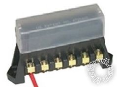
Ideally I only want FOUR terminals (which is already one more than I expect to need) but I can't find any one-in-many-out with fewer than six terminals.
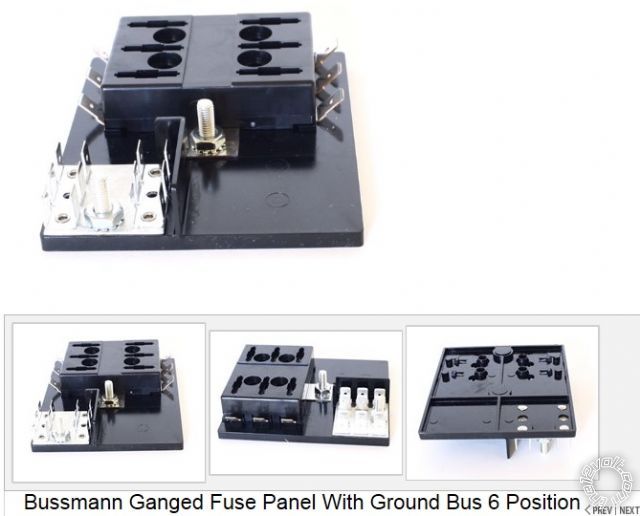
Anyway - I like the first flat black one the best, because it also offers a ground bus...which is going to further simplify and condense my wiring.
My next choice would be the second flat black one. Both look like an easier fit inside a die-cast box.
And my third choice would be...well...the third one.
Is there any advantage (or disadvantage) to any one of these options? Any features or possible problems that are not obvious from the photos? I've never worked with anything like this...but it certainly looks appealing!!
A big thanks to 'Ween' for steering me in this direction!!
Posted By: Ween
Date Posted: December 25, 2013 at 12:15 PM
For the power input, something such as https://www.onlinecomponents.com/ bussmann-cooper-c29091.html? p=10804917. Or build one with shoulder washers (nylon washer with a step machined on one edge/end).
Slip a bolt through, secure with flat washers and nut.
A ring terminal with multiple wires attached can distribute the power to individual relays. A single wire could distribute to an internal fuse block, output of the fuse block to the relays.
Sockets and terminals, pigtailed relay sockets or individual terminals for connections to your relays.
Input and output connections are one by a feed through barrier terminal strip. Individual terminals should be good for 15A each.
If the receiver is to be mounted underhood, the box (being aluminum) would probably shield reception if the receiver is mounted internally. A plastic case of similar style would be one option.
Mark
Posted By: Ween
Date Posted: December 25, 2013 at 12:34 PM
And a shoulder washer...a bit overkill for the application; https://www./itm/ WORKMAN-CB-RADIO-ANTENNA-SO -239-STUD-MOUNT-REPLACEMEN T-NYLON-WASHERS- BULK-/121176591696? pt=US_Radio_Comm_Device _Mounts&hash=item1c36b00d50
Application showing washer in use; https://www./itm/Workman- SM2-Brass-3-8-x-24-Lug -Terminal-Type-Stud-Mount- CB-RADIO-Antenna- /370954745110? pt=US_Radio_Comm_Device_Mounts &hash=item565ea03516
The case would be in the stepped down portion between the metal ends.
Posted By: ronemca
Date Posted: December 25, 2013 at 9:43 PM
"Hmm - I think I'm going to..."
I look like an ignorant ass*** because I am not taking suggestions.
 But that is not the case, gentlemen. I don't see myself mounting a post thru any sort of box. Not only because it introduces additional/superfluous/unnecessary connections, but also because it creates at least one more place for corrosion that needn't be present, because...
I have a two-piece silicone-lined firewall pass-through which will permit me to run my 8g feeder straight from the battery to the distribution block in one uninterrupted length.
If I can't ground the box by its mounting screws (and ground my relays to the inside of the box) I should be able to bring a GRND wire out the same pass-through to chassis GRND.
Admittedly the end result will not be completely waterproof (as it likely would be with your suggestions) but it'll be damn close. And a lot better than what I have NOW.
Besides - this is not a creek-swimming Humvee we're talking about here; if I am submerged deeply enough that my relay box is in danger of being swamped I'll have bigger things to occupy my mind than a few wires under the hood!
All this aside, I wouldn't have been looking in this direction without your smart & patient suggestions. So - thank you! I am most grateful.
BTW - do any of you have an opinion and/or first-hand experiences to share re: the three blocks I pictured above?
Posted By: Ween
Date Posted: December 25, 2013 at 10:00 PM
Posted By: ronemca
Date Posted: December 25, 2013 at 10:53 PM
Overbuilding is always my preference! And future-proofing, too!
Posted By: Ween
Date Posted: December 26, 2013 at 6:11 AM
Posted By: ronemca
Date Posted: December 26, 2013 at 7:31 AM
Posted By: Ween
Date Posted: December 26, 2013 at 5:56 PM
https://electronicsclub.info/diodes.htm
Posted By: ronemca
Date Posted: December 26, 2013 at 11:06 PM
Posted By: ronemca
Date Posted: December 27, 2013 at 7:43 PM
And I actually found a SPST relay with a diode wired inside...which I thought was kinda cool. And it was fairly inexpensive too; $5.65 + tax, but when I got it home and had a closer look I realized it had no mounting rail/tab...nor does it have a 15mm slot. So if I'm gonna use it I'll have to hot-glue it into the box, which seems less than ideal. Since I also bought a 10-pak of diodes...I think I'll return the protected relay and pick up another SPDT with a plastic mounting tab. That way all four relays will be the same. I will probably still squirt a dab of hot glue beneath each one when I install it...but I'll also drill a small hole through the project box and run a short bolt thru to tie the relays in position.
And I had intended to utilize the pre-wired sockets with pigtails [again] but I decided not to because:
a) the pigtails seem to be incorrectly configured; the heavier-gauge wire is on the coil terminals instead of the switched terminals
b) the wire that connects to the #30 terminal is black and the 87 is red, which strikes me as being bass-ackwards, and that'll bug me to no end
c) the interlocking style of socket is pretty bulky compared to making my own direct-to-spade wire harnesses, which matters because I'm trying to keep the box reasonably small
I realize that whoever may be reading this probably couldn't care two hoots for how I'm doing, and I completely understand that. I'm just thinking out loud in the hope that if I sound like I'm going off the rails...somebody will pipe up!
Posted By: Ween
Date Posted: December 27, 2013 at 7:57 PM
Posted By: ronemca
Date Posted: December 27, 2013 at 8:17 PM
In fact, none of the three that I currently own have mounting tabs; just the interlocking slides & grooves. But three out of four relays have mounting tabs, so I will stick to small nuts 'n' bolts...a dab of hot glue...and individual wires.
I am really stoked about this little project! I look forward to laying out the wires and securing it all inside the little box. The majority of the processes are not new to me, but the idea of the containment enclosure definitely is! I have always tried to do jobs like under-hood wiring neatly & carefully, and for the most part I think I do alright. But this whole project box scenario represents one of those Aha! moments in ones life where you find yourself branching out along a new & interesting line of thinking. ANd I am VERY pleased & grateful that you have shown me this fresh challenge, Mark. Thank you!
Posted By: ronemca
Date Posted: December 28, 2013 at 4:37 PM
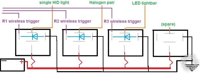
I have begun the wiring by inserting the diodes into the circuit in parallel across the coil terminals as shown. The actual science is a bit fuzzy, but I'm trying to grasp it.
As I see it, the diodes do not (cannot) block any electricity when the coil is energized because:
a) the electricity is flowing through the coil from + to - and effectively "bypassing" the diode
b) there is not (or should not) be any energy flowing "backwards" from the NEG side of the relay anyway
But -- at the instant the coil is DE-energized -- there is residual energy in the coil that could theoretically cause problems. And the sudden discharge/collapse/burst of this residual energy is blocked/dissipated by the diode so that it cannot travel...to...where, exactly?
When the coil is DE-energized, the residual energy in the coil is expected to "loop" "back" through the diode...and thence deplete itself by running in a closed loop until dissipated. And this is intended to "shield" the upstream components (in my case, a wireless switch) from that trace of reversing energy.
However...
The trigger wire remains attached to the POS side of the relay all the time. And if the diode is wired in parallel across the coil terminals...it too is therefore attached to the trigger wire all the time.
So...
Assuming that the flow of electricity "exits" the coil at the NEG side when the coil is energized, when the coil is DE-energized, does the residual energy in the coil continue to flow in that same direction? If yes, then most of it will go to GROUND, and any tiny bit that tries to sneak back through the diode will be blocked...and therefore NOT reach the wireless switch. :)
But is it possible for it to "leak" backwards? (reverse direction?) If so, then it will encounter the K end of the diode, which will allow it to pass through the diode and re-enter at the NEG end. Which is okay. But it will also encounter the trigger wire. So what's stopping it from travelling upstream back to the wireless switch?
Posted By: Ween
Date Posted: December 28, 2013 at 5:58 PM
Posted By: ronemca
Date Posted: December 28, 2013 at 7:34 PM
Ween] wrote:So I did understand it correctly. (There may be hope for me yet!)
Electricity follows the path of least resistance, which in this case is the diode. It could flow to the control circuitry (wireless switch) if the diode wasn't present.
Thanks, Mark.
Posted By: burntkat
Date Posted: December 29, 2013 at 12:59 PM
My wiring was getting rather alarming, to be blunt. What I did was looked into marine power distribution equipment. I specifically wanted something that would take the weather, was protected against shorts, and was decidedly anti-bling (I deplore chrome, gold plating, etc.. basically anything you see that would be found in an autosound competition vehicle).
The Blue Sea brand of distribution panels and fuse panels are pretty much the last word in all of these requirements.
Having said this- I am reminded that I still have the nasty "two relays taped together and butt-crimped into my harness" assemblage on the passenger's side, so will be doing that up proper today. I HATE crimp terminals, they're only suitable for temporary use (which apparently in my case means something like 6 years ;) ) unless they're also soldered. I can abide crimped ring terminals for ground or attachment to a bussbar, only if they are also soldered and heatshrunk.
But hey- you're talking to an Engineer who left mobile electronics to literally go do installations on Nuclear aircraft carriers and submarines. So to me the only way to do it right, is to overdo it. I build replacement battery cables out of 2/0 welding cable with silver-soldered lugs, then heatshrink with marine-grade heatshrink (which contains an adhesive, making the assembly completely watertight).
I have *never* had anything I build for more than temporary use come back for rework. Yes, it takes more time to do each connection this way-- but when I'm done, I'm *done*!
Posted By: ronemca
Date Posted: December 29, 2013 at 3:17 PM
It's interesting that this was posted just now, actually, because during the last 36 hours I have been educating myself about solderless terminal crimping (and the associated tools). As with almost every "technical" activity, there as a big collection of backyard mechanic -calibre tools...and a smaller collection of hi-grade I-make-my-living-with-these-tools tools.
** Just as an aside, I went through this same adventure with my RC helicopter electrical issues. And I discovered the most fantastic process I've ever seen (and which I use exclusively to this day) It's called "Anderson Power Poles" and let me tell you - it is the bomb. You buy the proper tool for the contacts, and you never look back.
Anyway - it's no secret that the common plastic-sleeved crimp terminals for 12v work are sub-optimal in may respects; I don't know anyone who LOVES them. But yesterday & today as I was poring over articles and reviews online I discovered that - if you do it right (with the right parts, the right tools & the proper technique) those things are fine. They're used more extensively than I would have thought in aeronautics, too. And -- let's face it -- there really aren't that many alternatives at the 22g to 16g level!
So - I learned that the "typical" combo pliers (the ones that cut, crimp, strip, [supposedly] cut small bolts, call 911 if you fall down etc. - and often come with an assortment of 100 crimp connectors) stamped out of 1/8" thick metal...are crap-ola. And I can't say I'm surprised to hear that!
Some of the pros say that the shallow concave sculpted jaws are one of the biggest negatives, because it's so difficult to CONSISTENTLY deliver the exact amount of force to compress the ring just right to hold securely without crushing (which increases resistance) The answer? Ratcheting pliers.
Huh?! Did you say "ratcheting" pliers?! You mean the exact same style that I use for the aforementioned process-from-heaven? (Anderson Power Poles)?!
Yup. And -- just like those other ones -- (and to be frank, to my ongoing frustration) you can spend anywhere from $100 -ish...right down to $16 to pick up a pair of your own. But let's not open that particular can of worms.
This actually got its start two days ago because -- when I went to buy the relays -- I also picked up some waterproof "flag" insulated solderless terminals. Hmm - flag, eh? These'll free up a little space inside my project box!
But I was dismayed to discover that:
a) the inner metal sleeve is manufactured out of a crush-proof Molybdenum/Titanium alloy
b) the aforementioned crap-ola crimpers cannot be used, because the cutting jaws would split the grippy part of the connector! (because the barrel is at right angles to the terminal)
I went ahead and made up a couple with a vise (insert maniacal 'I-win-again' laughter here) but I was soon crawling the 'net for a better option.
I finally found these:
_terminals.jpg)
"Electrolux!" I shouted.
No - hold on - it was "Eureka!"
So I'm trying to find a pair that I can afford without taking a fifth mortgage on the house. So far it's looking good, but obviously I don't want the flag equivalent of crap-ola! So I am wearing my skeptics beanie and reading lots & lots.
Posted By: burntkat
Date Posted: December 29, 2013 at 3:57 PM
I don't crimp the contacts on for any of these, however- I just silver-solder them. You'll find literally thousands of pages on the web where supposedly-educated people go on at length about how a non-crimped connection will eventually fail as there's no mechanical bond. Well, yes there is- a properly soldered terminal IS a mechanical bond by way of the wetting action of the solder. They'll say that if the connection heats up, it will liquefy the solder and let go. Well, look into the temperature required for that to happen- if your connections are experiencing that kind of temperature (without the components having caught on fire from other problems) then you have done something massively wrong in your design of the build. Simply put- these concerns are BS.
Now will I hammer-crimp a large-gauge ring terminal on, and then solder it? Sure- *if* I am in a hurry and can't find my "third hand" to hold things in place while I solder, and the terminal I am using is not designed to slide into a housing (thus necessitating clearance issues that can arise from deforming (crimping) the terminal. In other words, I'll only do it for ring terminals like you'd use on a starter. But I won't ever *just* crimp it and put it into production. You get less current flow that way, more heating of the connection, more opportunity for water and contaminants to enter (especially a concern in the environment a starter works in, for example)with the ensuing eventual failure of the connection. Solder it so all visible copper is wet with solder, heatshrink over that, and use the same connection for a lifetime.
Posted By: burntkat
Date Posted: December 29, 2013 at 4:10 PM
There's actually a pretty darn good ratcheting crimper available at OReilly's. I bought it about 6 months ago when I had a quick job on a neighbor's boat (he didn't want everything soldered together, long story!) and couldn't find my old Stake-on crimpers (FYI- the Stake-On and Klein crimpers like this: https://www.ironworkerstool.com/v/vspfiles/photos/Klein%201005-2.jpg are the only non-ratcheting crimpers that would pass inspection on the jobs I did for the Navy). The ratcheting crimper at Oreilly is this part, I believe: https://www.oreillyauto.com /site/c/detail/SG00/18900 /N0221.oap?ck=Search_ N0221_1362822_-1& pt=N0221&ppt=C0371
The handles on mine are yellow but it is otherwise identical.
Whatever hand tool you use for mechanically-connected wires, keep them lubricated both for protection and ease of use - both of which contribute to consistent performance. That gets us into another discussion, though. I'll leave that for another time, and just say I use Froglube for anything not involving an internal combustion engine... everything from my guns to my hand tools.
Posted By: burntkat
Date Posted: December 29, 2013 at 4:29 PM
I recommend using this:
https://www.bluesea.com/ products/category/ PowerPost_Connectors/ PowerPost_Plus
It has a 3/8" stud in the middle, approx. 6 (or is it 8, I am going from memory of my build) smaller screws for the branches in a ring around it, all of which are electrically insulated from the base, and conductive to each other. It also includes a boot for the main connection, and when you assemble it all (crimping and soldering the ring terminals to connect to the branches, then heatshrinking over the terminals as I've already gone into way too much discussion about :D ), there is very little opportunity for a short to occur to ground.
As always- fuse or CB (circuit breaker, preferred) within a foot of the battery to protect the vehicle (so something in the neighborhood of 100-amp+ ampacity), and each circuit individually- which gets us to my next point:
https://www.bluesea.com/ products/category/ Fuse_Blocks/ ST_Blade . There are versions with or without a bussbar for the ground connections. I use part number 5035, as we're dealing with a built-up 4X4 in my case- the bussbar really is only needed when you're doing some marine work- as the boats tend to be built of non-conductive fiberglass, so you need somewhere to ground everything. The 5035 uses commonly-available automotive medium-format blade fuses (ATO or ATC), has a latched cover to protect the circuits, and if you use it in combination with Smartfuses (which have an LED in parallel with the main circuit to indicate when they've blown), it only takes a glance to check the status.
Seems like you're using all of this on a 4X4 as well, as you're discussing large-format HIDs and such. I have to ask- why stick with the wireless remote system for these? Why not just hardwire them (in this case meaning forego the wireless fob inside the vehicle for a toggle switch controlling the relay pack you're referring to).
Posted By: burntkat
Date Posted: December 29, 2013 at 4:45 PM
It seems like you're wanting to do this partly to keep the wiring neat for the relays, making service and troubleshooting bad relays in future, much easier.
I've been through that, too. Long ago I used to solder directly to the relay (stupid!) and then I went through a time when I used solderless female crimp-on terminals with relays- which made servicing the circuit much easier, so long as I was able to change one lead at a time, and never took two leads off of a relay at once.
A couple years back, I found these relay sockets on Ebay (yeah, I know- but there is some gold out there!) from a vendor that went by "TheInstallBay". Let me see if I can scare them up for you....
Yup, here they are:
https://www./itm/10X-The -Install-Bay-RL3040-12V- 30-40-AMP-Bosche-Style-Relay -w-Socket-10-Pack-/321166484999 ?pt=LH_DefaultDomain_0&hash =item4ac703a607
Now those are pretty generic looking relays and sockets, right? Look closely- the bases all snap together (yet are easily disassembled) which makes working with relays MUCH easier. Now you build them into modules you need, label the base (I label the back of them with a Brother labeler) and you can remove every relay you've put into your vehicle at once, if need be for servicing- without worries of confusing wire mess on reassembly. More's the point, when you have everything in service, all of the relays are connected together- which makes them super easy to bolt down to the vehicle- I use #10 self-drilling screws into sheetmetal, and done. I will usually even ground the coil side to the holddown screw if I am not using it for trigger.
You can spend a lot more on this stuff- but this works extremely well, is overbuilt to a satisfying degree, and looks about as stock as you're apt to get it. Now there is an available solution from Bussman that not only looks OEM but is actually used by several OEMs, but then you're getting into being nickled and dimed for every contact, waterproof plug, and so on. I don't know about you, but I've had my 4x4 in situations where I was about to ingest water (so the engine was almost submerged, and the switchgear was completely under), and even so the lights and wich still worked just fine. I think the most important concern, electrically speaking, is for the lamps, winchmotor, and relays to be waterproof- everything else is going to be fine if it gets a little wet.
On a sidenote, might need to pick your brain about your lighting choices- I am still on the fence if I want to go HID for my aux lighting, or just stick with the dependable old Hella 500s I've been running for years. I have time yet, though, as I still need to finish up a few things on the solid axle swap- like build a bumper to mount the lights and winch to!
Posted By: burntkat
Date Posted: December 29, 2013 at 5:13 PM
ronemca wrote:
....I don't see myself mounting a post thru any sort of box. Not only because it introduces additional/superfluous/unnecessary connections, but also because it creates at least one more place for corrosion that needn't be present, because...
I quite agree, having been the route of the insulated through-stud. I ended up removing it and drilling out the hole for a simple rubber grommet
ronemca wrote:
I have a two-piece silicone-lined firewall pass-through which will permit me to run my 8g feeder straight from the battery to the distribution block in one uninterrupted length.
Someone's been browsing in the boating section! :)
ronemca wrote:
Admittedly the end result will not be completely waterproof (as it likely would be with your suggestions) but it'll be damn close. And a lot better than what I have NOW.
Actually, if you're using the assembly I think you are, you may be interested to note that they ARE completely waterproof when used for single cables. In fact there are several US Navy ships with the superstructure penetrated for HELIAX cable with those connections, that I personally placed there. They've had no problems at all. But yeah, I wouldn't use it on a submarine...
ronemca wrote:
Besides - this is not a creek-swimming Humvee we're talking about here;
Having done my share of Humvee driving through slop in the US Army, I Can tell you- they are FAR from waterproof!
ronemca wrote:
if I am submerged deeply enough that my relay box is in danger of being swamped I'll have bigger things to occupy my mind than a few wires under the hood!
Holy crap, someone else on the Internet finally "gets it"!
ronemca wrote:
BTW - do any of you have an opinion and/or first-hand experiences to share re: the three blocks I pictured above?
I think two of the blocks are actually the same, from different perspectives.
I have both of the ones I can discern as different units in the pics above, in my toolbox. When I was going through this concern with my build, I bought them with the intent that they'd be "The solution". They aren't.
Concerns: The metal parts are all unprotected- no plastic covers or such. This includes the base under the stud for supply to the block, and the base forming the spade connections for the block. It would be very easy to short this to ground while working under the hood. I don't believe this would be a concern for moisture, with the possible exception of coming across the right solution of suspended salts and contaminants in a hole you're traversing- as you may know, water is actually an insulator- it's the contaminants suspended in solution that make it conductive. Honestly, water as a shorting medium for what we're building probably is much ado about nothing. But it's entirely possible to short across these units to ground if working under the hood and you're not prone to follow the old adage of "disconnect the battery whenever you open the hood" (amateurs!)
So no, I won't use them. But I'll make you a deal if you want them. As they sit now, they're wasted money and will end up in the trash.
Posted By: burntkat
Date Posted: December 29, 2013 at 5:20 PM
Ween] wrote:
It would be a 1N400* series diode...1N4004 is fine. Connect the cathode (banded) side of the diode to the positive side of the coil, anode to the negative. On a bosch type relay, terminal 86 is typically the positive, terminal 85 the negative. More info can be seen here:
https://electronicsclub.info/diodes.htm
You might want to go back to diode school:
https://www.the12volt.com/diodes/diodes.asp
I will of course recheck this with my DMM, but I went through this last night while building my system on the bench...
Posted By: burntkat
Date Posted: December 29, 2013 at 5:26 PM
burntkat wrote:
Ween] wrote:
It would be a 1N400* series diode...1N4004 is fine. Connect the cathode (banded) side of the diode to the positive side of the coil, anode to the negative. On a bosch type relay, terminal 86 is typically the positive, terminal 85 the negative. More info can be seen here:
https://electronicsclub.info/diodes.htm
You might want to go back to diode school:
https://www.the12volt.com/diodes/diodes.asp
I will of course recheck this with my DMM, but I went through this last night while building my system on the bench...
Oh, hell.
I may be doing some rework in my system, looks like.
This is why I shouldn't be near a DMM or a soldering iron when I need sleep..
Posted By: Ween
Date Posted: December 29, 2013 at 5:32 PM
Posted By: burntkat
Date Posted: December 29, 2013 at 5:54 PM
ronemca wrote:
In fact, none of the three that I currently own have mounting tabs; just the interlocking slides & grooves. But three out of four relays have mounting tabs, so I will stick to small nuts 'n' bolts...a dab of hot glue...and individual wires.
Just throwing this out there, from my "the way I do things" files....
If you're going to be mounting these in a weather-protected area (and I don't count under the hood as weather-protected unless it's going in an enclosure), and don't have other mounting options, use Velcro. I am presently wrapping up the benchbuild part of my alarm and remote start, and all of the components going in the cabin are using Velcro to attach to each other, or the body in the case of the backup battery.
The relays for door locks and domelight supervision are interconnected as previously mentioned, and will be screwed to the body in the neighborhood of the driver's footwell. The CH2, CH3, and AUX channel relays will be mounted somewhere else, haven't finalized that yet. CH3 is my remote start trigger, so it may well be disconnected from the others and tiewrapped under the dash in the vicinity of the radio.
I would prefer not to just hang the control modules under the dash on tiewraps, but the proper way will have to wait for a bit until I replace the dash.
Posted By: burntkat
Date Posted: December 29, 2013 at 5:55 PM
Ween] wrote:
where is diode school?
I'll let you know when I find it and have completed it, apparently. :)
Posted By: Ween
Date Posted: December 29, 2013 at 5:57 PM
Posted By: burntkat
Date Posted: December 29, 2013 at 6:10 PM
ronemca wrote:
Okay! I think I'm on the right track here. Absolutely everything I know about diodes has been uploaded into my brain in the last 18 hours or so, so bear with me!
OK, have to ask, what are you using for these diagrams- it could help me in both my hobbies and my work.
ronemca wrote:
But -- at the instant the coil is DE-energized -- there is residual energy in the coil that could theoretically cause problems. And the sudden discharge/collapse/burst of this residual energy is blocked/dissipated by the diode so that it cannot travel...to...where, exactly?
Apparently I am fuzzy on these, too- but I am pretty comfortable with this part of the theory:
Diode coils form an electromagnetic field, which is what actually does the physical work. Now, electromagnets and radio frequency are related (don't ask me to go into that, it gets pretty far into physics, and my head may explode!). When an electromagnetic (heretofor: "EM") field is rapidly collapsed without anywhere for the field to go (as in taking one side of the electrical field away), the energy is dispersed into an EMI (electromagnetic interference) burst (a very low-grade EMP <electromagnetic pulse> that can be coupled into any nearby components.
Comes down to it- the diodes don't so much protect the device which initiated the EMI burst (they do), but they also protect the other devices upon which they are installed.
This all would get us pretty deeply into physics, RF theory, and antenna theory believe it or not. Like many things in electronics, it's one of those things that you may not completely understand, you just have to shake your head and say "I believe" at some point, and proceed accordingly. Kinda like which direction current flows. ;)
ronemca wrote:
The trigger wire remains attached to the POS side of the relay all the time.
Not if you're using negative-trigger, it doesn't...
ronemca wrote:
And if the diode is wired in parallel across the coil terminals...it too is therefore attached to the trigger wire all the time.
Physically, yes.. but let's look at a pushbutton switch on the dash to activate the relay. When the relay is deactivated, the wire going to the switch is physically there, but neither going to ground nor +. It's literally detached from the electrical system.
Posted By: burntkat
Date Posted: December 29, 2013 at 6:31 PM
Posted By: Ween
Date Posted: December 29, 2013 at 6:46 PM
Posted By: burntkat
Date Posted: December 29, 2013 at 6:55 PM
burntkat wrote:
Ween] wrote:
It would be a 1N400* series diode...1N4004 is fine. Connect the cathode (banded) side of the diode to the positive side of the coil, anode to the negative. On a bosch type relay, terminal 86 is typically the positive, terminal 85 the negative. More info can be seen here:
https://electronicsclub.info/diodes.htm
You might want to go back to diode school:
https://www.the12volt.com/ diodes/diodes.asp
I will of course recheck this with my DMM, but I went through this last night while building my system on the bench...
Please ignore the idiot that made the post questioning the post regarding the orientation of the diode. Ween is right of course.
I misread, misunderstood. I thought he was putting the cathode to the positive side to facilitate current flow (which of course would be wrong, as it won't flow in that direction, it's specifically there to BLOCK.. this is why they call it a BLOCKING diode, dummy!)
Sorry for the confusion. If it helps any, I think I got myself more confused than anyone.
Posted By: ronemca
Date Posted: December 29, 2013 at 9:51 PM

I'm probably going to pick up the one for the flag terminals, but I noticed that some of the other styles appear identical but for the jaws (which are presumably replaceable) so I wrote to a couple of the sellers to ask if they sell jaws, and I'll just swap out the jaws depending upon my project.
Posted By: ronemca
Date Posted: December 29, 2013 at 10:09 PM
As is often the case, my advisor(s) either are or have recently/repeatedly been involved in projects of far greater calibre than mine! Nevertheless I am learning a lot in a short time, and remain confident that my evil plan will work just perfectly.
I hear you on the hook 'n' loop, but will be carrying on with the plastic project box...mounted under the hood...and containing four relays, a 4-slot fuse block, a handful of peel 'n' stick tie-downs and an 8 (or possibly 12) -position terminal block.
I will mark & drill for the "normal" 15mm relay mounting tabs and run a small bolt through the box for each. I will do the same for the fuse block. I will secure the terminal block with hot glue or possibly double-sided tape, but may ultimately drill&bolt instead depending upon how secure it feels without bolts.
I will daisy-chain four of the adjacent contacts on the terminal strip...and piggyback onto the fourth screw a longer "primary ground" wire which I will pass out through the watertight firewall grommet and secure to chassis ground outside the box.
I will feed the box with a single 8g hot lead from the battery - fused outside the box.
I use MS Paint for my sketches.
Posted By: ronemca
Date Posted: December 29, 2013 at 10:38 PM
My wireless switches -- when remotely activated -- output 12v along a trigger wire which I have connected to the POS side of my relays. The NEG side of my relays go to GRND.
I have affixed a diode to each relay with the band [K] side on the trigger/POS terminal...and the [A] on the GRND terminal.
And someone -- probably Mark -- mentioned earlier that I could use fairly lightweight wire for "some" of the connections. I agree -- and I am already doing that to a degree...but would be grateful for some verification:
I realize this is load-dependent, and I also realize that within reason, it's impossible to be too big when it comes to cabling in this application, but given that we're basically talking about aux lighting pairs here...
Inbound power to the whole box (as mentioned) should be robust; 8g
Outbound power (per relay) should be - say - 16g
Inbound trigger can be in the range of 22g -> 16g
Ground (per relay) can be 22g -> 16g
"Primary ground" should be - say - 12g -> 10g
My internal ballast HID is a 50W, therefore should draw just over 4A.
Eagle-Eye 50W
My pencil beams are Hella 4000x @ 55W/ea. and should therefore draw just over 9A in total.
My LED Light bar (which I am picking up later today) is 120W (40 x 3W) but I'm not so sure it draws like a "normal" 120W load draws. But if so, I suppose I'm looking at a 10A load.
So - until I put something onto the spare circuit (R4) I intend to utilize a 20A fuse in my 8g supply line. Except for showing off -- which I VERY RARELY do -- all the lighting systems will not be active simultaneously, but in the event that my 20A fuse blows I will feel comfortable stepping it up to a 25A.
Posted By: Ween
Date Posted: December 29, 2013 at 11:13 PM
Anything larger than 20 gauge for relay coils is overkill, although some use 18 gauge. The 18 gauge being able to take more mechanical abuse.
For pairs of lights controlled by one relay, independent runs to each light would be better.
Is the light bar to be installed in the rear of the vehicle? If so, 14 gauge is a better choice.
Wire gauge is dependent on distance to load as well as current drawn. More than enough info is available online.
Posted By: burntkat
Date Posted: December 29, 2013 at 11:34 PM
What is the vehicle this is going in, out of curiousity? It is sounding more and more like we are similar sorts of guys, so my money is on a 4X4 of some sort- possibly a Rover?
I just relearned a lesson I picked up 20-some years ago while doing installations: when benching (prefabticating) the system out before install, don't wrap ANYTHING in electrical tape until it's all soldered and tested.
I have a diode backwards, apparently, and have a pile of wasted electrical tape at my feet as I take every bit of it back off.
Posted By: ronemca
Date Posted: December 30, 2013 at 9:59 PM
(Good call!)
Yes - I am intending to lighten the gauge of some of the wiring when I do the overhaul of the system. (Some/most of my low-power runs are thicker than necessary) However...we have dropped 15 degrees in the last 18 hours to around -10C, so there'll be no driveway fiddling for me for awhile!
Posted By: burntkat
Date Posted: December 31, 2013 at 5:44 PM
Got any pics?
Posted By: ronemca
Date Posted: January 01, 2014 at 2:41 AM
Posted By: burntkat
Date Posted: January 01, 2014 at 12:47 PM
Posted By: ronemca
Date Posted: January 01, 2014 at 2:07 PM
As with all things, there is a very wide range of prices for these things -- and I am a firm believer in getting what you pay for -- but this is just one small step above a toe in the water. A test application to see if the concept will perform/fit/last as well as I hope it does. That's not to say I expect to throw it away in three months...but neither do I expect it to deliver "handsomely" in light of what I paid. [:D:]
I plugged it in downstairs [in the dark] and it seems to throw a fair amount of light, but I have said the same thing about certain hi-calibre flashlights...only to later be underwhelmed when deploying it in a more "real-world" application.
In light of the weather -- and the sluggishness of my progress on the project box -- I'm planning to temp attach a cig lighter plug for some outdoor tests.
Posted By: burntkat
Date Posted: January 01, 2014 at 7:33 PM
LEDs are advancing rapidly, and gaining momentum. I have replaced every bulb on my truck except for the dash and main drivers (headlights and spots) with LEDs, and honestly there are better bulbs on the market now, cheaper, than what I bought in 09.
I fully expect in 5 years to be able to get a high-performance bulb for H4 and similar incandescent applications that will work as well as the incandescents, for under $30. Meantime I am going to keep running my Hella 500 driving lights (they work very well, and I like the look) and am looking for a small fog lamp- I've seen projector assemblies for under $50 on Fleabay.
Posted By: ronemca
Date Posted: January 01, 2014 at 9:26 PM
You say you want fog lights...but then you reference "projectors". These are mutually exclusive. Please expand.
Posted By: oldspark
Date Posted: January 01, 2014 at 9:48 PM
(I know H4 LEDs exist and there are HIDs than can be retrofitted, but I'm talking about a proper lighting system - not one that dazzles oncomers, ruins shell & lenses, and loses quality by putting up with old reflector/lens systems. LEDs for other lighting generally does not suffer the same problems.)
Posted By: burntkat
Date Posted: January 01, 2014 at 11:10 PM
Re: LED replacement of existing bulbs: just like I can buy an upgrade (Hella, Cibie, et al) that bolts in place of my original 6054 sealed-beams and lets me use an H4 bulb, surely there will be an assembly released to upgrade to LEDs. I realize that "in the Engineer's world", the housing made for $givenbulb does not work with $givenreflector. I also realize there are cheap, sub-optimal, aftermarket housings to adapt from 6054 sealed beams to H4s. I have them in my truck.
My truck is... err.. "slightly modified"... (factory suspension cut off, solid axles front and rear, 6" of suspension lift, hydroboost braking... to just give the biggest mods). So my headlights are a bit up there. I've NEVER been flashed for blinding oncoming drivers, mostly because I am running a white bulb (blue bulbs are about the stupidest thing you can run- look at the physics of how our eyes work), but because I took care to properly aim them.
So while I agree that these aren't optimal, I also know that the cheap $60 upgrade puts *A HELL* of a lot more light on the road, safely, making things more visible and making my vehicle safer for everyone involved.
I've also had people tell me there's no way I can possibly design a suspension better than the factory, "they have experts who are paid to do that". Well, there's that.. and there's the fact my truck drives much better than it did stock.
See, I'm a weird person- I follow Heinlein's axiom about experts:
"Always listen to experts. They'll tell you what can't be done, and why. Then do it."
Posted By: oldspark
Date Posted: January 02, 2014 at 1:11 AM
And each LED has its own reflector & lens, hence total "headlight" replacement.
But when prices are acceptable, I'll upgrade my halogen headlights to LEDs. I never considered HIDs acceptable (in my case) and certainly now IMO they are past their use-by date.
BTW, fogs are technically a low flat spread whereas projectors aren't (afaik).
But with 1,000Lm LED torches available for under $100 (retail) I'd expect plenty of options for projector (spot) applications.
Blue headlight bulbs - yeah, a great idea. A subset of white light; we are most sensitive to green; and of course blue would never refract differently to white thru a lens... Alas guns are banned here so I just put on my 200W spots and aim for any blueish headlight that dazzles me.
Cheap is relative. Cheap used to mean cheap price. I was blown by how good my cheap rectangular NARVA 150 x 85mm spots were. I reckon they outdid my quality 145mm (5-3/4") spots!
And of course these days, consumables etc are cheap. Same for LEDs. To think I can buy 5050 or 3528 SMD LEDs for 10c each (in roll form).
But automotive LED spotlights were around $500 a couple of years ago and now they seem to be under $200. And the uptake of LEDs in general has been huge... I expect LED headlights to be reasonably affordable fairly soon...
PS - I totally support Heinlein's axiom, however don't confuse them with people that say "they have experts who are paid to do that"... LOL - that is such a ignorant else stupid statement!! (Maybe it was made by "experts" from other fields? That would be typical!)
Posted By: ronemca
Date Posted: January 02, 2014 at 1:30 AM
burntkat wrote:Well, then! Allow me to repay your kindness with a little info to fascinate you whilst expanding your knowledge!!
Re: fogs vs projectors: Haven't done all my homework yet. What it comes down to is, I want a small, powerful fog light. Not some $25 at Walmart Blazer job, but not some $200 item, either. Preferably with a yellow tone, as to me, it gives me the best return in terms of visibility in fog.

The usurious tithes collected by various agencies in association with cross-border shipping (the Cdn. government, various couriers, CanPost) are commonly & erroneously called "duty", when in fact most of the time they are taxes and/or brokerage fees. Likewise, the yellow-hued lights on the front of a vehicle are commonly & erroneously called "fog lights", when in fact that descriptor speaks to a beam pattern more than it does to a light [colour] temperature.
Fog lights typically project a very wide, very shallow (top to bottom) beam pattern. Think of those street-cleaning tanker trucks that cruise around spraying water out of several nozzles. The water sprays in a pattern very similar to the light throw/pattern delivered by good quality fogs.
The prevalence of yellow fog lights is mainly because they tend to be more easily visible by other drivers...as opposed to making it any easier for their owners to see by. This is by no means absolute; certainly there are people who feel that their yellow lights penetrate dense fog better than their headlights, for example. But...
The other factor that is significant is the [optimal] mounting location for fog lights relative to the road surface; the lower the better. And it is that factor -- more than the colour of the lights, that contributes to that widely-held belief.
Sadly, it is usually impractical to mount fog lights really close to the ground, because they are far more susceptible to damage from curbs, pavement irregularities & driveway entrances/exits. This limitation is even worse on trucks - especially 4x4's.

The partial answer? Purchase good quality SMALL Lights that can be mounted low without too much housing dragging on the asphalt. And if the lights you choose have clear lenses...swap in amber bulbs!
Hella used to have some pretty nice small lights that have a "FF" prefix in the p/n. They're likely still making those. Also look at PIAA.
Posted By: ronemca
Date Posted: January 02, 2014 at 1:36 AM
(and please forgive me if I am rambling on about stuff you learned 25 years ago)
The ideal [colour] temperature for yellow fogs is 4300K.
The blue-ish HID's that many annoying people cruise around with are 8000K (approx.) and upwards of 10,000K they start to look purple.
Posted By: burntkat
Date Posted: January 02, 2014 at 5:46 AM
I know that fogs are wide flat beams, and honestly I don't know why I said "projector" when I meant precisely the opposite. Brainfart of the day.
I also know that fogs are more a function of the light pattern than the color, color being used largely for other driver's awareness- that's the largest reason I want the fogs, although I do feel I can see better in a foggy situation with the yellowish light.
I didn't realize that the lower mounting position was better for fogs. This has me thinking that it wouldn't be too difficult to mount them on my axle - bears further study!
I didn't realize the Hella fogs were specified by FF prefixes- this is a great tip, as I'd love to have another set of Hellas on my truck, being immensely pleased with the 500 pencil beams (might be misspeaking here- they're a driving light, very much a "pencil" of light as opposed to the OEM assemblies).
-------------
"Always listen to experts. They'll tell you what can't be done, and why. Then do it. - Robert A. Heinlein"
Posted By: oldspark
Date Posted: January 02, 2014 at 10:21 AM
But in any case, the higher the lights, the more that will reflect back to the driver. Hence "keep it low" with minimal upward beaming. IMO ronemca's description of a street cleaner's spray is excellent.
And IMO it is the fog light's 'spray' that is the most important; the color is secondary. (Hence my tolerance of modern cars with 'so called' fog lights despite them - technically - not being locally legal {in Aussietralia} to use in conjunction with other main beams.)
But the yellow is a duality. Easier to see by others, but likewise better for illumination - especially in fog prone areas that may use yellow lane marking etc (not that white lines are good in snow either).
I trust ronemca's claim that 4300K is the ideal (yellow) color for fogs - IMO that seems about right. (Hey man, that's testing my recollection of the CIE color chart etc - and that was the 1931 version! Not that I've used that since the late 1990s.)
Alas when I drove competitively I did not use fog lights. Instead it was full on driving lights - in my case spots - and picking the appropriate gap between the trees to drive thru. (Rally driving by fog lights would have limited speeds to well under the 100+kph that was required for reasonable results.)
Posted By: burntkat
Date Posted: January 02, 2014 at 10:33 AM
I'm one of the rare Southern US men that Can. Not. Stand. that crap they call NASCAR... you want auto racing, let's drive through some twisties at 100+kph with the risk of falling off the damn mountain!
-------------
"Always listen to experts. They'll tell you what can't be done, and why. Then do it. - Robert A. Heinlein"
Posted By: ronemca
Date Posted: January 02, 2014 at 1:21 PM
burntkat wrote:Hmm. Methinks they would be 'WAAAY too vulnerable there...particularly since you presumably do NOT stay on nice, smooth asphalt at all times!!
Thanks guys < snip > I didn't realize that the lower mounting position was better for fogs. This has me thinking that it wouldn't be too difficult to mount them on my axle - bears further study!
burntkat wrote:Admittedly I've not looked at them for a spell, but AFAIK the "FF" prefix is NOT related to the "fog" application; I believe it's merely a model designation. Further -- and again I'm awakening long-slumbering neurons here -- the FF -series of lights are small, round-lensed lights. Ergo incapable of throwing a very flattened beam. (I was instead trying to think of small-ish, durable, decent-throwing lamps that could be outfitted to project YELLOW light for your application)
I didn't realize the Hella fogs were specified by FF prefixes
burntkat wrote:You are correct - the 500's are not a pencil beam...although that designation is more ethereal than...say..."fog light" or "driving light"...both of which are designations that have some well-documented qualifying characteristics.
...the 500 pencil beams (might be misspeaking here- they're a driving light, very much a "pencil" of light as opposed to the OEM assemblies)
I agree that the Hella 500's are excellent lights (as are the 4000x's I installed) but once you've experienced the Eagle Eye HID's you will be awestruck. NOW we're talking pencil beams!! If you could somehow freeze the beam pattern and detach it from the front end of the light you would end up with a white telephone pole about 200 feet long. And the diameter of your frozen pole would only flare slightly as it lengthened too - just like an actual telephone pole. (The beam pattern remains impressively tight even far away) It's amazing.
Posted By: burntkat
Date Posted: January 02, 2014 at 2:49 PM
but I found these, and they look like they're exactly what I'm looking for:
https://www.summitracing.com/ parts/hla-h71010331?seid=srese1&gclid= CNvcz9Gu4LsCFahj7AodqmIA-g
Cheap, too!
-------------
"Always listen to experts. They'll tell you what can't be done, and why. Then do it. - Robert A. Heinlein"
Posted By: burntkat
Date Posted: January 02, 2014 at 2:54 PM
https://www.amazon.com/Optilux-H71010291-Model-Halogen-Projector/dp/B0002MA3NU/ref=pd_sbs_auto_6
That's a Hella light, sold by Hella, and they're calling it a projector...
-------------
"Always listen to experts. They'll tell you what can't be done, and why. Then do it. - Robert A. Heinlein"
Posted By: ronemca
Date Posted: January 02, 2014 at 5:34 PM
Yeah - I had a look. AS is often the case, they're mis-using the term "fog" [light] when they really should be saying "auxiliary" [light].
I followed one of the additional 'you-might-wanna-look-at-these-too' links at the bottom of the page, and you should see the description! Clearly a [very approximate & awkward] translation from a non-English text. (And also mis-uses the term "fog")
In any case, it looks like you found a winner! But before you pull the trigger, do have a look at the small round ones (they might be called "DE" or DE Xenon") But you may not be able to swap in an amber bulb.
That said, don't forget you can always apply amber film to the lens! Serves dual purpose; colour change AND protection!
Posted By: oldspark
Date Posted: January 02, 2014 at 7:29 PM
I had a look at those oblongs in the https://www.summitracing.com.....odqmIA-g link above and they look ones I bought ~15 years ago to augment my then car's crap lowbeams.
I recall referring to them as 'glorified parkers'.
HOWEVER, I doubt they are Hella. They certainly do not have the same lens (mine are "plain") and I can't see what bulb it is, but there is no significant heatsinking so I doubt it is halogen (55W).
I might pull them off later and check detail. I never bothered removing them from round-tuit car #2 because they were such crap.
Certainly the Hella/Optilux units pictured look like they mean business. Really need to try before buy else find good pics or reviews etc.
Posted By: burntkat
Date Posted: January 02, 2014 at 8:03 PM
Of course this is rather "cart before the horse" as I still need to build a bloody bumper to mount them on!
It'll be like the garage cleaning project - "well, I found this, bought that to go with it, and since I then had everything and ran out of excuses, I had to build that to use them all".
I do have a legitimate question about pinswitches I'd like your opinion (more like educated input) on, though. I'll make another post in just a moment, please do check if you have a moment.
-------------
"Always listen to experts. They'll tell you what can't be done, and why. Then do it. - Robert A. Heinlein"
Posted By: burntkat
Date Posted: January 02, 2014 at 8:10 PM
If you will take a few moments to check this out, I'd appreciate it...
Look for the recent thread, in this forum, "one pinswitch to rule them all"
(why yes, I have been doing too much writing lately.... why do you ask??)
It concerns multi-zoning a single pinswitch. We used to do this back in the day for various security systems in facilities, but I can't recall if I need more components in this... I don't think I do.
-------------
"Always listen to experts. They'll tell you what can't be done, and why. Then do it. - Robert A. Heinlein"
Posted By: ronemca
Date Posted: January 03, 2014 at 7:03 PM
burntkat wrote:
Not to pollute your thread ...
burntkat wrote:Okaaay...
Gents:
If you will take a few moments to check this out, I'd appreciate it...
kat - you're getting decidedly elderly in your old age.
Posted By: burntkat
Date Posted: January 03, 2014 at 7:09 PM
ronemca wrote:
burntkat wrote:
Not to pollute your thread ...
burntkat wrote:Okaaay...
Gents:
If you will take a few moments to check this out, I'd appreciate it...
kat - you're getting decidedly elderly in your old age.
Entirely too true.
My apologies..
-------------
"Always listen to experts. They'll tell you what can't be done, and why. Then do it. - Robert A. Heinlein"
Posted By: ronemca
Date Posted: January 03, 2014 at 7:09 PM
The excitement builds!
I have reached a decision re: splitting my 12v feeder inside the box: The 8g wire I'm using is of course stranded, and I have therefore elected to split the bundle into four [fairly] equal branches. I'm going to solder a short 16g jumper to each of these four branches, and then solder the entire mass together. (Obviously a nice, neat heat shrink condom will finish the job) That'll be the very last step in the build (the rest is done) after which I will post a pic or two.
Said pics should become available in the VERY wee hours of Sat. 01/04/14.
Posted By: oldspark
Date Posted: January 03, 2014 at 7:29 PM
(Tho if there is physical security and each split has its own fuse...)
Posted By: ronemca
Date Posted: January 03, 2014 at 10:58 PM
And yes indeed each of the four branches has its own dedicated fuse. Which reminds me...
When choosing the optimal fuse amperage, am I selecting the closest available that is less than the actual load?
I ask because 4A seems laughably small for the 50W HID, and/but 10A seems high for the 120W LED bar. OTOH, 10A seems just about right for the twin 55W Halogens.
Am I using the right formula?
Posted By: ronemca
Date Posted: January 04, 2014 at 1:11 AM


Posted By: oldspark
Date Posted: January 04, 2014 at 1:28 AM
Ooops - too late!

A fuse rated "less than the actual load?"...
No - because then the fuse would constantly blow wouldn't it? (Ha ha, I finally get the chance to get sarcastic and dig the knife way in....
) [ BTW - I rarely go to the trouble to include emoticons. To do so would require the utmost care and concern by me.... ]
The "Rules":
A fuse must be rated to handle the load - ie, at least equal to the load.
Usually that is the max expected load - eg, at max volume, or max current (light output) at highest voltage - but you might decide lower is ok (eg, 5A for a 10A amp where you don't expect to go higher than ~1/4 max volume or half full output) - not that you can do that with lights.
And there is a general fusing/protection/wiring design rule - namely that fuses (and wires & relays etc) should not normally run at higher than ~70% of its rating, though sometimes 90% may be designed (and sometimes 110% in reality - noting that a fuse or breaker may last indefinitely on a 110% loading (10% overload)).
Hence for a 50W HID, IMO...
Assuming 50W HID means output hence ~60W input...
Or using the usual ROT (rule of thumb) - divide the power by 10 to get current - hence 50W/10 = 5A.
[ FYI - The 10 is simple, and it tends to factor in the "conversion" from output to input (at say 80% efficiency) or that 12V really means up to 14.4V etc and that rating may be based on old 13.8V car voltages if not newer 14.2 or 14.4V, or even 12.0V. ]
So 5A. That fits in well with st'd fuse sizes (unlike 4A), but then if we apply the 70% rule it means a 7.5A or 10A fuse.
But now the important thing - WHAT are we fusing? (Or rather, WHAT are we protecting?)
It might be to protect the source - ie, battery or alternator - but that's not relevant here. (Let's assume some "master" upstream fuse or flink (fuselink) does that.)
Usually it's to protect the load. And that's where people get con-fused. (Ah yes, a Master of Punnery.]
The "load" is anything downstream from the fuse, and in our cases they are rarely for equipment protection - ie, HUs, amps, CPUs etc have their own fuses specifically designed to protect that equipment.
Hence our protection/fusing is almost always for the distribution - ie, wires, connectors, relays.
And the fuse rating (Amps) must not exceed the smallest rating downstream - ie, a 10A cable can have a 10A or 7.5A or 5A or 250mA fuse but NOT a 15A or 30A or 200A fuse.
Note however that a fuse only protects its distribution until the next fuse. I'll call that segmentation...
So, your design...
You know you need (say) 5A for each 50W HID. Hence you need cable rated for (at least) 5A.
You might use 5A cable and hence a 5A fuse. I'd probably use a 10A or larger cable but could then use a 5A or 7.5A or 10A fuse (anything up to the cable rating).
Remember - that fuse is to prevent the wire from flaming if it shorts to GND. The fuse must blow before the cable has a chance to get too hot...
And why use larger than necessary cables? To minimise the voltage drop. Or because it's what I happen to have on hand and isn't too expensive or big or heavy...
Now, not that I know your design (hey man, emoticons are one thing, but to actually read what has previously been written in a thread... c'mon, get real!!), but...
Two "5A HIDs" (ie, each with their 5A fuse & cable or 10A fuse & 15A cable etc) could be joined to a 10A distribution which might be a 10A fuse & 10A cable, or 15A or 20A fuse with a 20A cable etc.
Likewise all loads can be joined.
One danger you have is the splitting of the main feeder's core. Since they are not individually fused (upstream), if any were to short to GND or if an individual load exceeded that split's actual current carrying capacity...
An outright short is probably not an issue since its current should be many times the upstream fuse rating, but it is any overload less than a direct short that is the danger.
Provided a split's downstream fuse is rated reasonably below the split's capability, it may not be a big issue. IE 8G. Assume a 60A rating. 4 splits in theory about 15A each (not that that logic always follows!). But you would not use a 15A downstream fuse... 10A maybe. The splits may be uneven, hence 13A or 12A etc. But also we do want the fuse to blow before the cable melts in an overload situation (ie, not a direct short). And since a fuse takes s time to blow at x overload and a cable takes t time to blow at the same x overload, we want to ensure the fuse time s is less than cable time t, hence in simple terms that the fuse is reasonably smaller than the presumed split rating.
Simple eh? Of course most would say that such splits are unacceptable for the reasons I outlined and hence a DB (distribution block) or similar must be used - and professionals may have no choice on the matter - but I try to point out that "protection" can be physical instead of (or as well as) electrical, and there are different protection modes (overload, shorts, equipment protection).
And I've seen enough installations that follow the rules that are IMO outright dangerous - eg, battery safety isolation switches on the +12V side, or useless and dangerous alternator-battery fuses as per big 3 upgrade on integra fuse box?. Even oft quoted rules like fusing within x mm/inches are not really rules at all - I prefer 'as close as practicable' to the battery (noting that practicable is the key word and subject to expert and legal opinion...).
But I have written much on the above issues before - as well as on using self resetting circuit breakers for critical lights (and probably having them on separate distributions) - and I've repeated way too much here.
As to your 10A for twin 55W HQs, you'll have figured that's probably a bit low (but see comments re my 10A CBs below).
Though 55W HQs are 55W input, the 'div by 10' rule is till good as it factors in distribution NOT running at 100% of rating (tho the div-10 rule tends to assume EITHER an 80% efficiency ELSE a vehicle's voltage variation, whereas fuses etc might normally be consider a 70% loaded device).
Hence 2 x 55W = 110W => 110/10 => 11A, hence a 15A fuse and cable. 10A may be ok, but why cut so close?
Likewise the 120W LED => 12A => 15A distribution.
Hey - does that work out nicely? All cabling from the feeder could be 15A (or higher) rated cable with 15A fuses.
Of course that depends on how the 8G is rated and hence what each split can carry. (Different people use different cable current rating methods & tables. I never use them since I work from what I consider an acceptable overall voltage drop and that is always less than what the industry considers acceptable.)
BTW - it doesn't matter if the total of the downstream (split) fuses exceed the feeder cable rating since the feeder's fuse (60A?) will protect that cable. Of course if that blows. you lose all.
[ FYI - hence my car's main beam distribution via huge flinks intended never to blow (2 of; I can't recall if they are 50A or 60A or 100A; nor if I split as hi/low or left/right, tho probably the latter) which then feed relays each with self resetting circuit breakers. Though at the moment I'm using 3 relays for 6 filaments (4 lights), I intend to revert to my traditional dedicated relay per filament. The breakers are rated at 30A (for 2 100W inner highbeams) and 10A for the others that feed 65/55W H4s (normally they'd be 15A breakers assuming 100/90W or 100/55W H4s, but I have not had problems with mere 10A breakers (fuses) on what is obviously at least a 2x55W load (probably 55+65 = 120W or maybe even 65+65 = 130W). But I recall replacing the original 15A CBs with 10A CircuitBreakers to see what would happen... ]
Anyhow, that's my design theory along with actual observations.
BTW - my cabling well exceeds load requirements and fuse/breaker ratings. It met my design of no more than 0.5V less [across the bulbs compared to the source (ie battery or alternator output).
Always nice writing a quickie before a sat'dy night gig.


PS - I started writing this before your last reply. I wonder why I took so long to write?
Posted By: ronemca
Date Posted: January 04, 2014 at 1:58 AM
In fact, what I ended up doing is re-joining the 4-way split into one. (I had intended to do it like sketch #1, but it ended up as #2)

I still haven't decided whether to install a main feeder fuse. It seems like overkill to me, but I suppose there's always a tiny chance that the main feeder could GRND somewhere between the battery & the split. I guess.
< scuttles off muttering >
Posted By: burntkat
Date Posted: January 04, 2014 at 7:39 AM
I have 3/0 welding cable going to the back of my truck for winch and jumpstart use. Since winching can induce loads up to 300A, I am running a 400A fuse at the battery- it's not there to protect the winch motor, it's there to protect the cable and vehicle in event of a short of the cable to chassis.
While there's certainly some science in oldspark's approach, I disagree with a few points. Here's what I do:
*Always* protect the distribution within a foot of the battery- for the same reason I fused my welding lead as above. In this case, the load doesn't matter. Take the wire gauge and the length (of entire circuit, ground and positive) and look it up on an ampacity table. Fuse should be a fast-blow sort, rated near the top of that range (a little over is perfectly fine, as there is a very large safety factor inherent when you're using fine-stranded cable, which you definitely should be).
This protects the battery, cable, and your car, only. Fusing of loads is handled at the loads.
To figure out the amps required for your load- take the watt rating, divide by 12 (nominal voltage in our systems, with rare exception). I don't know where he's getting the "divide by 10" bit. It's close, but not correct- Ohm's Law is what we're dealing with here.
When you get a value that is between commonly available sizes- step up.
In my case, I am running two 55W driving lamps. 110W total, obviously. Divide by 12, you end up with 9.2A. Well there's a 5, 7.5, and 10A fuse commonly available- I'm running the 10A and am perfectly well-protected. Additionally, I sized my load's supply lines to accept the biggest commonly-available bulb (there are 100W H3s on the shelf at every parts store), so if/when I change out for those, I will then have 200W, divide by 12 = 16.6A. I'll throw a 20A fuse in there and be done.
Now in the event of a motor, there's Inrush Current to consider- among other things, you have to overcome the inertia of the motor, which requires a huge spike- but that's not what we're doing here. The only possible application (other than OEM starter motor) would be a winch. I don't know any manufacturer that fuses the car's starter, nor any winch manufacture that advises it. I've never seen a fuse on a winch. Another story altogether, though. Best guess is they're used so seldom, and are built for the abuse, that the fuse just isn't necessary.
Yes you can get MUCH deeper into the science of this subject- but it's not rocket science. We're building a truck here, not a Tactical Data System on a Nuclear Aircraft Carrier. (I should know ;) )
-------------
"Always listen to experts. They'll tell you what can't be done, and why. Then do it. - Robert A. Heinlein"
Posted By: burntkat
Date Posted: January 04, 2014 at 7:43 AM
In fact, I am going to steal an idea from you- the clear shrink over diodes. I've done some unnecessary rework on the present build simply because I couldn't remember if that was a solder joint or a diode under the heatshrink - I cut my diode leads short, and once my solder joint is made and under shrink it's impossible to tell (without a meter, which needed a battery) if there's a diode under there. I'll continue to use opaque shrink or tape on my connections, but the diodes will be shrunk with clear shrink to make this a no-brainer.
-------------
"Always listen to experts. They'll tell you what can't be done, and why. Then do it. - Robert A. Heinlein"
Posted By: burntkat
Date Posted: January 04, 2014 at 7:55 AM
The solder and shrink trick to split the main feeder cable to the 4 loads is neat, and if space is an issue it sometimes has to be done- but in a vehicle there's always an alternative- move the split upstream to a physical location with room for the following, or to the battery terminal:
I'd have installed an insulated stud (the sort I posted a link to earlier, from Blue Sea) and used ring terminals on all the connections, then bolted them together.
This way you KNOW there is sufficient cable cross-section for you to just look it up on an ampacity chart and figure out the maximum current it can take.
As you've done it, even if you were very scientific in dividing the cable into sections for the soldering, you still have some variance. I suspect that you eyeballed it, which is fine but you'll have yet more variance.
While probably not an issue, it is possible that you may be exceeding the ampacity of the junction you've made.
Would I lose sleep over it? Not really. But I wouldn't do it again.
-------------
"Always listen to experts. They'll tell you what can't be done, and why. Then do it. - Robert A. Heinlein"
Posted By: burntkat
Date Posted: January 04, 2014 at 8:05 AM
I went through this with my headlights several years ago- and realized that the factory runs the headlights from battery, through engine compartment into cabin, through the switch and back to the headlights- all via 16GA wire!
When I realized this I backprobed the bulb when in use- I was only getting 9.5V to the bulb!
This got me started on reworking the heavy loads in my vehicle, as the factory had done a sub-par job. I now have each filament of the OEM lights on its own relay and fuse. I could have ganged the low and high beams each on one relay- but then if I lose a relay I lose an entire circuit (thus, losing headlights while I need them. Yikes!)
I definitely like a good CB, but for the expense and packaging concerns, a fuse works just fine.
-------------
"Always listen to experts. They'll tell you what can't be done, and why. Then do it. - Robert A. Heinlein"
Posted By: Ween
Date Posted: January 04, 2014 at 9:03 AM
With the ohms law, Oldspark is dividing by 10 instead of 12. Then he is sizing the fuse after that result which results in a value that is 20% higher. Makes the math simpler, and ending up with pretty much the same result. You take 110W divided by 12..get 9.2, fuse at 10A. He would take 110W divide by 10..get 11A, fuse at 15A. You are sizing your fuse close to the rated load. Look into a modern vehicle fusebox, you'll see circuits "overfused" according to you. Now we know a fuse will carry a bit more current before it blows. As long as the wire is of proper size, I see nothing wrong. Now I'd fuse the lighting circuits independently, but that's me.
In the splitting of the feeder cable, 1-8ga = 2-11ga = 4-14ga.
Now say you erred in splitting them evenly and one ended up 16ga.
It's less than a 3" length of 16ga! I doubt you'd measure any significant voltage drop on that length at 30A.
On a construction note somewhat related. For another trick with using the diodes especially when using individual terminals. Bend the diode leads in a "n" shape with the legs as wide as the outside of the coil terminals. Lightly scuff the outside surface of the coil terminals with small file. Do this near the base of the relay. Locate diode across coil leads (Convention says term 86 is more positive than term 85). Solder the diode in place, trim excessive length. This can be tried with socketed relays, but there may not be clearance when the relay is reinserted into the socket.
Just a few thoughts.
Mark
Posted By: oldspark
Date Posted: January 04, 2014 at 9:55 AM
I explained why the 10 factor is used instead of 12. But it is also a simple initial design approach which often turns out to be quite accurate in practice.
For the exact design you would not use 12 (I can't think of anyone that would use 12V as the design voltage for 12V automotive etc systems), but 12.7, or 14.4, or whatever minimum voltage is applicable (11.6V, 10.5V, 8V etc) and also factor in any inefficiency, and then whatever overhead you want. Plus allow for manufacturing tolerances, temperature, etc.
All in all dividing by 10 (Volts) is easy and accurate in almost all situations. Only for borderline cases where f.ex the div-10 answer is close to a preferred value (eg, 14.5A or 15.5A) would you normally have to do the exact calcs to determine if a 15A cable & fuse will suffice, or if you have to go to 20A etc.
FYI - Div-10 (or div-20 for 24V) is a common automotive design ROT and you should find it is quite common. It is not merely something I have concocted.
And I think burntkat misunderstood what I wrote about not fusing within (say) 12" of the battery, else I expressed poorly.
If burntkat is correct, then his starter motor cable has a fuse. (No?)
And burntkat will guarantee that the fuse in the link I posted is safer than no fuse....? (No?)
And what distance will the "Rule" standardise on? I have often read legit sources that will claim 4" or 6" or 10cm etc (even if it means being on top of a battery!).
I merely tried to qualify any so-called distance rule so that it/they are not blindly followed. (Did I mention physical security/protection? Starter? No?)
And burntkat's first line omitted that the main feeder fuse is also to protect the feeder cable (though that should be clear from his later statements - if not mine).
But usually cable protection is the sole reason for fusing because many projects like this use cables too small to be much threat to the battery whereas if that cable heats or melts, you're in big trouble.
Re acceptable voltage drops, I was shocked to find that many automotive electrics references reckoned that "up to 3V" is acceptable (without any qualification). And that seems to be a traditional view...
These days with HIDs and (ballasted aka SMPS regulated) LEDs etc it's not as important (provided their highest current at lowest voltage if a constant power load is taken into account).
I may have decided my 0.5V max drop when rally driving where a 1V drop to halogens meant a significant drop in light output (far greater than for incandescents), but I use 0.5V as max desirable drop for heavy and such 'critical' loads. I might tolerate 1V when impractical to get less (not that I ever have).
For things like plain LEDs or bulbs or fans, a 3V drop may be acceptable. But 3V means 9.5V from a typical loaded fully charged battery (~12.5V ), or ~11.5V from a typical max alternator voltage (14.4V). Is that acceptable?
Re CBs - it costs under $10 for a (self resetting) ATS CB up to 30A (or mini-ATS CB up to 20A) which - being ATS - generally has no packaging (housing) concerns.
Likewise under $10 for up to 50A but they are typically stud terminals with mounting flanges to bodywork etc.
CBs larger than 50A can get expensive and awkward as burntkat suggested, but I have never needed them that big.
My largest self resetting CB for lighting (where you don't want fuses unless redundancy or fallback is provided) is presently 30A because of my single relays feeding 2 filaments, but normally it'd be 10A or 15A for 12V 100W or 130W filaments.
Otherwise my largest is 50A for my 2nd battery - I found that 30A ATS fuses would occasionally blow and - not being alarmed - meant risking a flattened 2nd battery or a warm fridge. And I'd only have to blow one flink to make a profit from that CB.
BTW - I prefer one relay per filament merely for alignment purposes, and sometimes for testing. Relays themselves are very reliable - moreso than filaments and most switches. And tho the self-resetting CBs may provide enough circuit recovery, my redundancy is mainly through source and signal splitting - eg highs & lows on separate main fuses and feeds (if using one relay for both sides); highs are the fallback for blown lows, and the flasher (pass) is the fallback for beam (hi & lo) signal failure.
I've avoided details for brevity but hopefully you'll understand my clarifications and maybe find support for the div-10 ROT.
PS Mark - I started my reply before your reply. Thanks for the "short bit" note on the split. I have oft pointed out that consideration yet overlooked mentioning it here. Bless clear thinkers and proof readers! And thanks for the rest.
Posted By: ronemca
Date Posted: January 04, 2014 at 11:09 AM
A fair bit of this is well beyond my experience/knowledge. When I got into RC [collective pitch] helicopters, I quickly discovered that my forte was most definitely fabrication & repair...as opposed to actual flying
I continue to gamely make a go of it (flying, that is) but let's just say that my flying skills produce a disproportionately large amount of opportunity for my - ahem - other skills.
This carries over into the current (nice one, eh?) adventure. I take great pride in the fabrication -- and have fun doing it -- but I am not as strong in the theory. That said, I am not so ignorant that I would blindly fire something up just because I'm proud of how nifty it looks! And that's why I am here; to bolster the areas of my skillset that I know are lacking. (Thank goodness I am rakishly handsome; clearly you fellows -- as gentlemanly & knowledgeable as you are -- have nothing to offer in THAT arena.) But I digress.
I have a handful of barrel-style fuses on hand for the primary feeder - I shall insert one in that line within 12" of the battery. This box may not go in for a bit, because it is brutally cold here (and to my ongoing frustration I still cannot find an indoor workspace) PLUS the LED lightbar is not even installed yet. Meanwhile, the single HID and the twin 55's are working perfectly. Hopefully it'll improve enough soon to get this done, since the completion of the enclosure has seen the lion's share of the job taken care of in the comfort of my basement!
Posted By: burntkat
Date Posted: January 04, 2014 at 11:38 AM
.. and if you're not using the actual input voltage (nominal, or measured) in that formula, you're not using Ohm's Law.
I don't want to take this convo off the rails (again), though, so I won't go further on that.
Suffice to say, the OP has done a very good job of this project, and I can't wait to see everything finished.
I'm off to see if I can find some more high-amp blade fuses, as this conversation has inspired me to build something I've had in mind for a while!
-------------
"Always listen to experts. They'll tell you what can't be done, and why. Then do it. - Robert A. Heinlein"
Posted By: burntkat
Date Posted: January 04, 2014 at 11:47 AM
oldspark wrote:
To address some of burntkat's comments...
I explained why the 10 factor is used instead of 12. But it is also a simple initial design approach which often turns out to be quite accurate in practice.
For the exact design you would not use 12 (I can't think of anyone that would use 12V as the design voltage for 12V automotive etc systems), but 12.7, or 14.4, or whatever minimum voltage is applicable (11.6V, 10.5V, 8V etc) and also factor in any inefficiency, and then whatever overhead you want. Plus allow for manufacturing tolerances, temperature, etc.
And the very moment you get out of a low-voltage realm, all of that goes out the window.
If we're going to share knowledge so that others may learn, let's teach them properly.
Example:
Going with the "/10" rule, someone learns the above and applies it to their automotive build.
Outstanding, wonderful, works great, lasts long time. I fully support it.
But once you step outside the low-voltage realm (which is going to happen in automotive use, thanks to hybrids and so on), you end up with the wrong answers entirely.
It's dividing by 10 versus dividing by the nominal voltage of the system. If you're going to practice engineering, practice engineering, not "about right, wild-ass guess".
-------------
"Always listen to experts. They'll tell you what can't be done, and why. Then do it. - Robert A. Heinlein"
Posted By: burntkat
Date Posted: January 04, 2014 at 1:31 PM
oldspark wrote:
Re CBs - it costs under $10 for a (self resetting) ATS CB up to 30A (or mini-ATS CB up to 20A) which - being ATS - generally has no packaging (housing) concerns.
I am curious about these. I wasn't aware there are self-resetting CBs in the same package size as an automotive blade fuse.
I've looked for "ATS CB" and am finding refrigerator-sized units. Obviously I am not searching for the correct thing. Educate me? :)
-------------
"Always listen to experts. They'll tell you what can't be done, and why. Then do it. - Robert A. Heinlein"
Posted By: Ween
Date Posted: January 04, 2014 at 5:21 PM
https://www.waytekwire.com/products/1366/Circuit-Breakers/&Type=Blade-&Reset-Method=Type-I---Automatic&Mounting-Style=ATO---ATC-Blade
https://www.delcity.net/store/ATO-:-ATC-Blade!Style%3Cbr%3E-Circuit-Breakers/p_151
Appears there are three types of circuit breakers: Type 1, 2, and 3.
Type 1 is described as automatic rest, 2 Modified, and 3 Manual.
While they do fit into an ATC/ATO fuse holder, they are significantly taller in profile. So the base is of the same size of course.
Posted By: burntkat
Date Posted: January 04, 2014 at 6:40 PM
Unfortunately, owing to the profile, the packaging is still an issue. But they're certainly much smaller than I expected.
-------------
"Always listen to experts. They'll tell you what can't be done, and why. Then do it. - Robert A. Heinlein"
Posted By: oldspark
Date Posted: January 04, 2014 at 7:37 PM
And who's talking about "getting out of a low-voltage realm"? I am talking about a common ROT used for 12V automotive electrics. I am not talking about calculating the current for a specific voltage and load.
Not meaning to sound facetious, but is your unawareness of ATS style CBs indicative of limited automotive electrical engineering experience? (Don't worry - I often lack such awareness despite being expert in certain fields - it's one of the hazards of using ancient learnings with deliberate (modern) ignorance, else boredom.)
That reminds me - I referred to ATS types fuses - I meant ATC (or ATO?). I normally just refer to them as blades (and mini-blades and micro-blades). Typical me - despite designing with discrimination (i2t profiling), I'm still sketchy on their technical name.
As usual I found a few such as ATO/ATC Blade Style Universal Circuit Breakers (only $3.84 each!) using 'blade circuit breakers' in google images. Not that I found the ATCs that were even smaller than that sample which are larger and can have 'stacking' issues (and I don't mean the micros or minis that Ween linked).
Note that the div-10 is not for any safety factor per se, it is simply a ROT that is used either when estimating input current based on output power (amps, HIDs, converters etc), or a load current that factors in the voltage variance of a vehicle. AFAIAAware it is an old rule from the days when 12V vehicles regulated to 13.8V and hence 13.8V was the "standard" voltage used for ratings - eg, a 55W bulb meant 55W/13.8V = 4A (3.98A) - not that they had constant current or constant power back then (did they?).
I don't know if there is a 'standard' voltage these days (that's my blissful ignorance) but I see 14.4V is often used, but so too 12.0V & 13.8V.
Of course input voltages are irrelevant for HIDs and certain LED lights. (And should be for big amplifiers yet many seem to imitate resistive loads according to their specs, but that's an old conversation.)
But the div-10 is not a final design. It is a first cut guesstimate. The final design needs its sanity check and confirmation against the user's max & min voltages with whatever safety margins or overheads are desired.
However it is amazing how often the div-10 calcs agree with the final design, largely thanks to rounding up to the next preferred value of fuse or cable etc.
Note too that I am using div-10 because there has been no specification of what the voltage range is, nor actual load input powers or currents (as measured - not based on nominal specs).
If you still don't understand what the div-10 rule is about, maybe you could give an example of your design - eg, for ronemca's 50W HID (or 120W LED) - and then we compare?
That's provided ronemca doesn't object - I'd hate to see his thread get too long.
Posted By: oldspark
Date Posted: January 04, 2014 at 7:50 PM
ronemca wrote:
... I quickly discovered that my forte was most definitely fabrication & repair...
Oh man I like your style. (And that's just mentioning ONE example!)
Damn it, maybe I will have to read previous posts in this thread. Bluddy Canadians - far too much in common with us Aussies (some unfortunate, but hey - I concentrate on the good things!).
Thanks ronemca for your comments. I admire those that do see the learnings and the discussion. But to still see it after pages of garble which sometimes seems to be or is contradictory, or merely mentions/scrapes some complex issue....
For my replies I advise to rereading and often to reread in sections ie, one bit or concept at a time. I do the one reply that has it all - just like books etc - however I leave the chaptering up to the readers. But whereas books are planned...
But I'll break for now - I need to visit a wrecker for my repairs. No, not breakages - I'm obviously a far better flyer than you - but due to the damned pathetic quality of my car parts. Honestly, you'd think a wiper assembly manufactured and fitted in 1964(CE) would last longer. It's not as if the wipers have wiped the road for the >1 million miles that the underbody has.
Oh well, they used to call it Jap Crap back then. I'm now beginning to see what they meant.
In the mean time I hope my our your humor improves.
Yours in all sincerity.
Peter.
PS - I simply cannot allow the 2nd last line (above 'Peter') to pass as is. 'Yours faithfully' or 'in good faith' may be acceptable, but certainly not 'sincerely' if it is taken to include other than my first 3 paragraphs.
I may at times assume too much familiarity and risk misunderstanding, but sometimes that and honesty cannot be risked.
Posted By: ronemca
Date Posted: January 04, 2014 at 9:38 PM
That said, I am not now -- nor do I expect to become -- involved to quite the degree that is being hinted at in this thread. (Ms. Kate Beckinsale occupies far too much of my attention here at the manor)
But if -- with the guidance and discussion that is being kindly offered here -- I can get this rig up & running without burning anything up, I will be a happy camper. [thumbup]
Posted By: oldspark
Date Posted: January 05, 2014 at 3:40 AM
Gents, I am VERY disappointed - there was not as much humor as I expected tho IMO Ween takes the prize with Diode School, 101 Semiconductor Lane (I thought it was Semiconductor Tunnel, Ling).
However the experience and tips made up for that. To see others that know of bad crimpers, soldering, etc etc.
And ronemca - you nailed the freewheeling or spike-protection or snubber diode across the relay coil. That was a quick learn indeed - you seemed to grasp it easily.
FYI - my summary is that the diode is normally reverse biased (does NOT conduct) so it has no effect on the circuit, but when a coil releases (is de-energised) it produces a huge -ve spike so that the normally +ve end (86) is more -ve then the GND or -ve end (85), and that can wreck attached electronics.
It also gives a nice kick if you'd like to put a finger on each of terminals 85 & 86 when you de-energise the coil.
Anyhow, that's when the diode conducts and hence shorts that -ve pulse.
And 12V/24V coils generally generate spikes up to ~200V, and hence 1N4004 (400V) or 1N4007 (1000V) diodes are used.
1N400x diodes handle 1A. The general guidance is that the diode should handle twice the current of the coil, and since most automotive relays like we are using are 250mA or less (hence needing a 500mA diode), the 1N400x series is fine.
So instead of generating a back-EMF (spike) of ~100V to -300V which will kill most semiconductors, it is snubbed to a mere ~0.7V which is safe. And as Ween wrote, will also reduce noise. (Good one Ween - I rarely think of that even though I had dash lights that would flash on when I turned off my highbeams.)
Incidentally, I hate relays with inbuilt diodes (variou$ reason$) and instead prefer to incorporate 1N4004/7s in the harness or socket.
And tho I usually don't bother because mine are mechanically switched, I may start including diodes as standard for the sake of noise suppression.
As to relays with inbuilt snubber resistors, IMO why bother - go it properly.
And that's a good segway... You all like to do things properly. And over design. (I won't say over-engineer...) IE - ensure it works, remains reliable, and is reasonable future proof.
YAY!
But like I said - impressive stuff. I thought long threads meant trouble. This is an (IMO rare) exception. Ok, some confusion about coil diodes, but so what? And I was worried about a metal case housing wireless receivers...
I like Ween's feeder cable splitting (1-8ga = 2-11ga = 4-14ga) as well as other great bits.
And burntkat has so many comments that hit home. (Obviously you must have flamed any cat deliberately - it certainly would not be accidental!)
And as to Sir OP - a quick learner with an interesting expression of humor.
Anyhow, I'll get back to burning some servos I got from the wreckers...
Maybe after some wine. (It was a warm sunny day until the smell of bushfires rode in ahead of real gusty chilly winds and black storm clouds that were quire scary. If only I had a drink for the road... (no! never.).)
Posted By: oldspark
Date Posted: January 05, 2014 at 3:51 AM
My 12V automotive 'equipment' design rules are 8-16V. If that HID608 has the same, then it's a 7.5A design (ie, 10A cable & fuse) rather than a 'typical' 5A design, tho IMO that'd be the same 10A circuit since I wouldn't bother with a 7.5A fuse etc.
However, since we all tend to overdesign - as well as keep to standard components (?), I think what I said before about 15A distribution for all the targets covers it.
Posted By: ronemca
Date Posted: January 05, 2014 at 10:49 AM
< scuttles outside to the frozen truck >
It is actually not too bad here today; 0ºC at ATM, having climbed from -20ºC 48 hours ago.
Posted By: ronemca
Date Posted: January 05, 2014 at 10:54 AM
I guess that's understandable given his extremely advanced age. (Hell - I bet when he went to school they didn't even have history class!)
Posted By: oldspark
Date Posted: January 05, 2014 at 3:55 PM
You irresponsible arrogant youngies spending time with your games and looking for papers 'cos you're so
But you'll get a break in a few days when I'll be disappearing again. And now that the post-New Year daily routine has restarted I'll be on the PC less.
Anyhow, I was merely gonna comment on your sandbox status - but something distracted me...
YES - it is very annoying not being able to edit to destroy the evidences. I think 50 posts are required?
But a warning - you can only edit (or delete) if your post is still the last one.
If someone has post-posted (...?? ante posted, suffixedly posted?), then TOO LATE, your post is locked.
Yeah - this site is cruel - they expect you to live with your mistakes forever for all to see.
[ Actually I like that - PROVIDED readers know that the must look further to see if there were any corrections. IE - on other forums I may strike-thru or demark, but never delete - I'll add POST EDIT dd/mm/yy comments with the correction or link etc. Qualification - editorials may simply be fixed (eg, spelling & punctuation) with a "minor edits' comment.
Maybe you can tell that I'm into traceability, like facing errors, and hate pathetics covering their tracks. ]
PS - don't forget the "Preview Post".
Posted By: ronemca
Date Posted: January 05, 2014 at 4:52 PM


Next I'll temp-connect a cord and string it back thru the door frame to plug into the cig lighter so I can see how it throws in the dark. However, that adventure will have to wait, because I want to weatherproof the various threads before any of the components are allowed to remain on the truck for long. (it's friggin' snowing again, and forecast to dip from its current daytime 0ºC to daytime -15ºC in the next 36 hours with rain/sleet/snow).
Posted By: ronemca
Date Posted: January 05, 2014 at 5:03 PM
During my search for this light bar, I did see some that had an extruded track along the back side...along which two (or sometimes three, if the housing was a long-ish one) stud-holders could slide.
That method of mounting would have been INFINITELY preferable to the one I ended up with. These stand-offs are really awkward, since I am mounting it on a tube as opposed to a flat[ter] surface.
Yes - I had to procure the pair of split-ring sleeve mounts, but that aspect is irrelevant. It just ends up being a lot of weight dangling out in space...relative to the attachment point. I therefore imagine it's gonna bounce a fair bit if the road is the least bit rough. And -- not surprisingly -- my vehicle rides like a truck. I don't mind it at all, but if it sets the light a-bouncing...well...We'll just have to see. Maybe I'll be pleasantly surprised.
That said, I do not expect to have it activated often, anyway. Next to the other lighting systems it will be pitiful, and may therefore be relegated to stationery working-out-in-front duty.
Posted By: burntkat
Date Posted: January 06, 2014 at 9:17 PM
I need to get my bumper and roo bar built... but it's not happening anytime soon- temps are getting down to 12 degrees tonight. That's quite unusual for us!
-------------
"Always listen to experts. They'll tell you what can't be done, and why. Then do it. - Robert A. Heinlein"
Posted By: ronemca
Date Posted: January 09, 2014 at 1:13 AM
Meanwhile I have the LED light bar temp-wired to a cig lighter socket plug - and my mounting mechanism is essentially ready to go - so I will try to get a couple of pics up this weekend...as it is supposed to climb close to zero deg. on the weekend.
Posted By: burntkat
Date Posted: January 09, 2014 at 3:45 PM
-------------
"Always listen to experts. They'll tell you what can't be done, and why. Then do it. - Robert A. Heinlein"
Posted By: ronemca
Date Posted: January 09, 2014 at 10:12 PM
I re-mounted the new LED Light bar to the brush guard again (properly this time - in a manner that could stay in place, should I decide to leave it to be exposed to the nasty rock salt etc.) and off I went to a dark stretch of road nearby. The first three pics are the LED light bar only. And then - when I was under the overpass, I shut down the LED bar & activated the HID headlights only just for comparison. I am IMPRESSED! 'Waay more throw than I thought I'd get.


Posted By: burntkat
Date Posted: January 10, 2014 at 8:16 AM
-------------
"Always listen to experts. They'll tell you what can't be done, and why. Then do it. - Robert A. Heinlein"
Posted By: ronemca
Date Posted: January 10, 2014 at 11:37 AM
On that same dark stretch of road, when I am adjusting the VERTICAL alignment of the pencil beam, I am trying to decide where I want the most amount of light. If it's a little low...I get a huge, brilliant white "pool" of light twenty feet in front of the grille. If it's a little high...I get nothing on the ground at all; it's all in the trees some number of feet above the road 100 yds. away!
So it's a slight compromise. The beam is so focussed, and reaches so far, that it is silly to have it exactly parallel to the road surface. Therefore I have to bend it downward just a little, so that it DOES hit the road, but maybe...150 FEET in the distance. So that's what I have, and it's good.
I followed the exact same process with the paired Halogens, except that they cannot project nearly as far. Therefore they hit the road...perhaps...75 feet in front.
These are very rough estimates, but you get the idea.
With the LED light bar it's difficult to find that optimum aiming threshold. I may be 'way off base, but it seems like the light throw is very finite; out to about 50 feet it's awesome...after which it seems to just fizzle. The result is that if I don't have the focal point hitting the road 25 to 30 feet in front...it/they just disappear. Yes - there is some wide-angle spillage from the 8+8, but the bright spot is gone (until I drive up fairly close to something, that is)
Mind you, this is only my first impression, and I have not driven with them on for more than two minutes. Perhaps my impression will change as/when I put some more miles on them on thinly-travelled back roads! Here in the near-city there is ALWAYS some schmuck approaching -- or upon whom I am gaining -- even at 4:00 in the friggin' morning!
Posted By: ronemca
Date Posted: January 19, 2014 at 6:19 PM

Posted By: burntkat
Date Posted: January 20, 2014 at 10:19 AM
I am curious how these behave, though- do they thermally cycle, is there a time delay, or does power have to be removed entirely from the circuit before they reset?
-------------
"Always listen to experts. They'll tell you what can't be done, and why. Then do it. - Robert A. Heinlein"
Posted By: oldspark
Date Posted: January 20, 2014 at 10:41 AM
Thermal delay based on severity (i2t).
Posted By: burntkat
Date Posted: January 20, 2014 at 11:12 AM
I know there are circuit breakers used in marine applications which reset once the supply is removed (ie: turn off the switch for the light, and turn it on again). They're called "auto reset" breakers.
In this case, "auto reset" meaning you don't have to go find the damn thing and push a button on it.
-------------
"Always listen to experts. They'll tell you what can't be done, and why. Then do it. - Robert A. Heinlein"
Posted By: ronemca
Date Posted: January 20, 2014 at 2:19 PM
* * Note ** NON-EXPERT speaking... [:)]
As I understand it, there are three types of auto CB's; Type 1, 2 & 3.
Type 1 is push a button to reset
Type 2 is power cycle to reset
Type 3 is "auto" reset after cool-down (no power cycle, no button) This is the type I purchased.
Posted By: ronemca
Date Posted: January 20, 2014 at 2:21 PM
oops - please remove the word "auto" in the first full sentence.
Also I missed the second colon in my smiley. (Geez - it'll be great to be able to edit!) [:D:]
Posted By: oldspark
Date Posted: January 20, 2014 at 3:49 PM
The PORs essentially need manual intervention - ie, the power recycle (whether programmed or timed or by solar array or manual trigger etc).
And POR types are generally not used for automotive etc applications - except perhaps for fridges and similar (where normally CBs are not recommended but may be desirable to avoid fuse replacement cost or labor).
Posted By: ronemca
Date Posted: January 20, 2014 at 4:23 PM
And...I would be keen to learn whether I have offered a correct assessment re: the three types of automotive CB's, please Sirs. [:thumbup:]
Posted By: ronemca
Date Posted: January 20, 2014 at 4:25 PM
(P)achyderms (O)ften (R)emember?
(P)eople (O)ughtta (R)ead?
Posted By: burntkat
Date Posted: January 20, 2014 at 8:46 PM
ronemca wrote:
* * Note ** NON-EXPERT speaking...
As I understand it, there are three types of auto CB's; Type 1, 2 & 3.
Type 1 is push a button to reset
Type 2 is power cycle to reset
Type 3 is "auto" reset after cool-down (no power cycle, no button) This is the type I purchased.
I'm even less than one, explaining why I asked. :)
Thanks for the intel- that's the kinda education I was looking for!
-------------
"Always listen to experts. They'll tell you what can't be done, and why. Then do it. - Robert A. Heinlein"
Posted By: oldspark
Date Posted: January 20, 2014 at 9:13 PM
I don't know about the type 1, 2, 3 etc. I have never used it and I suspect it may vary with the region or profession etc as do 1 wire alternators (meaning D+/L only aka 2 or 3 wire elsewhere) or SPDT aka changeover relays (aka 5-pin but 5 pin might be dual output SPST).
In my experience CBs are manual reset else auto or self resetting. As I said, reset after power cycling is rare and in my circles considered "manual" since it is NOT auto or self resetting - ie, they require another action (beyond the control of the breaker) to reset.
Posted By: ronemca
Date Posted: January 21, 2014 at 8:25 AM
burntkat wrote:And thanks for that; I take great pleasure from feeling as if I am contributing.
ronemca wrote:
* * Note ** NON-EXPERT speaking...
As I understand it, there are three types of auto CB's; Type 1, 2 & 3.
I'm even less than one, explaining why I asked. :)
Thanks for the intel- that's the kinda education I was looking for!
Posted By: ronemca
Date Posted: January 28, 2014 at 8:46 AM
ronemca wrote:Okay - I got this wrong; the Type II definition is correct, but the I and III are reversed.
* Note ** NON-EXPERT speaking...
As I understand it, there are three types of automotive CB's; Type 1, 2 & 3.
Type 1 is push a button to reset
Type 2 is power cycle to reset
Type 3 is "auto" reset after cool-down (no power cycle, no button) This is the type I purchased.
I did order the ones I wanted (sealed - no button - reset by themselves after cooling down) but those are actually Type I not Type III. Sorry.
Posted By: oldspark
Date Posted: January 28, 2014 at 4:49 PM
Yours IMO & experience are self or auto reseting breakers as opposed to manual resets or blown fuses.
Not suited for certain loads (fridges come to mind) but excellent for occasionally peaky loads (auxiliary battery feeds) or criticals like headlights.
Posted By: ronemca
Date Posted: January 30, 2014 at 1:25 AM
oldspark wrote:Absolutely correct, Sir.
< snip > Yours IMO & experience are self or auto reseting breakers as opposed to manual resets or blown fuses.
oldspark wrote:
<snip > ...excellent for occasionally peaky loads (auxiliary battery feeds) or criticals like headlights.
And they even fit into the little 4-slot fuse block!
So the project box is complete, and the various leads in/out of the box have been lengthened, soldered, heatshrunk & tie-wrapped. I have installed a six-conductor disconnect so that I can remove the box from the truck in seconds...should I need to perform maintenance.
The last steps are:
1) introduce the other side of the six-conductor disconnect into the aux lighting wires under the hood...
2) pull one of the two single-channel wireless switches and install the two-channel wireless switch...
3) strap down the box somewhere...
4) measure/cut/crimp the primary feeder from the POS terminal of the battery
But since it has been consistently 18-ish degrees (Cº) below freakin' zero - that's had to wait.
Posted By: ronemca
Date Posted: February 26, 2014 at 12:59 PM
Nothing has changed.
I work horrendous hours, and absolutely positively every single time there would have been a couple of hours to finalize this adventure...it has been so friggin' cold that I just can't get into it. It's insane.
I have put up an ad on the free classified site, and talked to all of my buddies - trying to find an INDOOR garage space for a couple of hours, but to no avail. Lots of people have double garages, but everybody has so damn much clutter that there's no room to do anything but squeeze out the partly-open door of whatever vehicle you park in there. AND the space is un-insulated and unheated.
I guess I would have been a little more willing to compromise if I had NO lighting solution...but I have full access to everything so far (it's all mounted and energized and working) so I CAN put off the upgrade until it's reasonable to work outside again. The way it's looking now, that'll probably be on July the 18th between 1:30 and 4:00 PM.
Can't wait!
Posted By: burntkat
Date Posted: July 15, 2014 at 8:08 PM
-------------
"Always listen to experts. They'll tell you what can't be done, and why. Then do it. - Robert A. Heinlein"
Posted By: ronemca
Date Posted: July 15, 2014 at 8:57 PM
Even more importantly (and surprisingly) it worked the first time!!! I didn't test it in any way - I just crimped and heat-shrank and tie-wrapped until everything was connected...re-inserted the main barrel fuse...and hit the buttons on the wireless remote one at a time. All three lighting systems activated just as they should. Immensely gratifying.
I couldn't have done it without extensive patience & guidance from M. Ween. Thanks, Man.
In fact, the job is not completely finished. Since I was futzing with it for the whole day...I ran out of time and daylight before I had a chance to properly stow/mount the two bundles (one being the project box, and the other being the two wireless receivers which are affixed to each other) They're in their final location (sitting beneath the K&N CAI filter) but I need to tidy up the wiring. Alot.

Posted By: burntkat
Date Posted: July 26, 2014 at 1:10 AM
I am just giving you hell, and hoping for more pics of the truck. I still haven't installed my alarm- but I have a good excuse- I got waylaid by a need to build and install a new engine for it. I've got the stock engine back together and it seems like it's undamaged (long story- BLUF: don't let a professional work on your junk- my oil pump FELL APART and was resting in the bottom of the pan!). I am building a smallblock V8 to go in its place, and this was all actually rather fortuitous. I did the solid front axle swap two years ago. If I hadn't, I'd have had to completely remove the drivetrain to fix this, since the factory front axle is 1" from the oil pan, making it inaccessible.
-------------
"Always listen to experts. They'll tell you what can't be done, and why. Then do it. - Robert A. Heinlein"
Posted By: ronemca
Date Posted: July 26, 2014 at 6:51 AM


The centre one is a 50W internal-ballast HID pencil beam. And boy - did I choose wisely on that! It maintains an impressively-tight circle/focus 'waaay out in front of the truck. Exactly what I was looking for.
The LED lightbar is 40 x 3W emitters. The outboard eight on each end have orange peel reflectors (for wide angle dispersion) and the rest are smooth for distance. Considering the price, this thing is awe-inspiring in terms of the amount of light it throws. Again - a lucky choice...since I had zero experience/exposure (I have not seen a single other one on anyone's vehicle in the last year and a half)
The Hella's are each 55W long-distance white. They were the first aux lights I installed, are were described as...chosen...and intended to be pencil beams. Sadly, they are underwhelming in this capacity. They throw a decent temperature of light -- and it's a reasonable amount of light -- but the focus scatters pretty close in. They are therefore used the least.
Posted By: burntkat
Date Posted: July 29, 2014 at 12:46 PM
-------------
"Always listen to experts. They'll tell you what can't be done, and why. Then do it. - Robert A. Heinlein"