latched on/off using constant input,
Printed From: the12volt.com
Forum Name: Relays
Forum Discription: Relay Diagrams, SPDT Relays, SPST Relays, DPDT Relays, Latching Relays, etc.
URL: https://www.the12volt.com/installbay/forum_posts.asp?tid=128233
Printed Date: April 01, 2026 at 10:22 AM
Topic: latched on/off using constant input,
Posted By: 01 Suburban LS
Subject: latched on/off using constant input,
Date Posted: August 13, 2011 at 9:23 PM
Hopefully this is possible. I would like to have two seperate 12v+ inputs trigger as 12v+ output. First trigger would be ignition power. Then when a second 12 volt source activates, it triggers the output. But here's the catch, when the second 12volt source turns off, I still want the triggered output to remain on until ignition voltage it cut.
Would this diagram work? But insted a constant fused 12 volt source, use a switched 12 volt source and nothing connected to "Pulse to turn off"?
Thank you.
Replies:
Posted By: oldspark
Date Posted: August 14, 2011 at 12:03 AM
Would this be simpler?
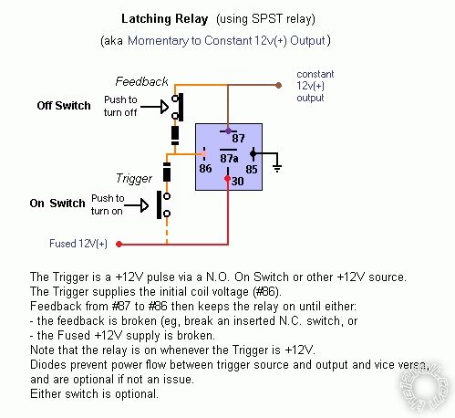
That's from latched on/off momentary w/ brake kill, though the feedback Off-switch isn't shown in the circuit diagram accompanying the above fig in that link, although it is described (ie, feedback link keeps relay energised until broken, or 12V POWER is removed from the circuit).
I have an updated cct diagram with the latch "Off" button shown.
In your case, if the Off signal is a pulse, you may have to replace the momentary off (normally closed) Off switch with an SPDT/changeover/5-pin relay - ie, #30 from the +12V output, #87a to the "latching" relay #86 and #85 to ground.
Note that the On trigger +12V can be any +12V, hence the dashed line to the +12V power.
It shows a pump as the load because this circuit was used for a fluid-level circuit. (Use to drain a sump, or by merely turning the "float" switch assembly upside down, a tank-fill aka "maintain tank level" circuit.) But a load is a load.
Posted By: 01 Suburban LS
Date Posted: August 14, 2011 at 11:57 AM
Im not sure if that would work. I'm not using any switches.
Turning on the ignition would give the relays power, but would not trigger the output. Then when I turn on my A/C and the compressor cycles on, the relays would trigger, turning my fans on. When the A/C cycles off, I dont want the fans to turn off until I turn the engine off. So once the fans are on, I want them to stay on, regardless if the system is automatically cycled on or off.
Posted By: oldspark
Date Posted: August 14, 2011 at 7:44 PM
In that case, omit the switches with the off switch being instead a short/link.
The IGN +12V is the heavy power source.
The on trigger is simply the AC +12V signal.
The relay turns off when IGN +12V is turned off.
Posted By: 01 Suburban LS
Date Posted: August 20, 2011 at 4:12 PM
If I'm understanding that correctly, wouldnt the A/C turning off also turn off the fans?
Posted By: oldspark
Date Posted: August 20, 2011 at 7:30 PM
No, not as long at the "fused +12V" input power is available.
The "feedback" link must be broken/opened to unlatch the relay (else the "fused +12V" input power removed).
Posted By: CutDog504
Date Posted: August 22, 2011 at 5:47 PM
What type of vehicle will this be going on? Maybe you can use the keysense wire as the turn off input trigger.
Posted By: 01 Suburban LS
Date Posted: August 23, 2011 at 10:40 PM
CutDog504 wrote:
What type of vehicle will this be going on? Maybe you can use the keysense wire as the turn off input trigger.
A 2001 Chevy Suburban.
Here is what I'm trying to accomplish.
I added electric cooling fans a few years ago. My Suburban originally had a belt driven fan. I used an OEM electiric fan assembly which consists of two fans. I also purchased an aftermarket harness to control the fans that works like how the vehicle would of been wired if it can with e-fans. The harness has three relays. And I also had the fan option turned on in the Suburbans ECU. The way it works is, once the engine reaches around 200 degrees the ECU sends a signal to the relays to activate the fans at 1/2 power. Once the A/C is turned on, it gives the relays a second signal via the A/C compressor clutch wire which gives the fans full power. The thing I dont like about that is the A/C compressor cycles on and off, which is normal. The problem is, the fans kick on and off as well and creates a heck of a draw.
What I am trying to accomplish is not have the fans cycle with the A/C compressor. Once the A/C system is turned on, I want the fans to stay on, regardless if it cycles.
Posted By: oldspark
Date Posted: August 23, 2011 at 11:04 PM
Again, my latching relay circuit.
Simple in principle. Only complicated by ground-switched controls etc, but there are many options there - invert the polarities in my diagram (use a dual-pole else 2nd relay if +12V power is required), invert the input signals (another relay, else transistor or FET etc).
|