the12volt.com spacer
icon

latched on/off momentary w/ brake kill


Post ReplyPost New Topic
< Prev Topic Next Topic >
airticulated 
Member - Posts: 10
Member spacespace
Joined: May 12, 2011
Posted: May 13, 2011 at 12:34 AM / IP Logged  
I am wiring a manual torque converter lock up switch for my tow vehicle. This is normally a simple task. One wire in the transmission solenoid is tapped and grounded manually with a toggle to lock the t/c. A 3.3 ohm resistor gets wired in line as to not trip a check engine light. Piece of cake. Why do it the easy way I say?
What I want is to create a latched relay so I can lock and unlock the t/c with a momentary button. While the t/c is locked I want a led to light up. If the t/c is locked and I hit the brake I want it all to turn off.
I know it is possible but my brain isn't functioning as it should currently so I have turned to the pros here. I have used your diagrams many times,and love the site. Long time guest first time poster! About time I say.
Can someone post up a diagram to clear my cobwebs! Thanks in advance.
oldspark 
Gold - Posts: 4,913
Gold spacespace
Joined: November 03, 2008
Location: Australia
Posted: May 13, 2011 at 12:54 AM / IP Logged  
Why not just a latching switch to control a normal relay?
Otherwise the following provides a toggle/latching signal, but you'd probably have to add a transistor etc to handle the relay's coil current....
latched on/off momentary w/ brake kill -- posted image.
hotwaterwizard 
Silver - Posts: 1,350
Silver spacespace
Joined: December 11, 2003
Location: California, United States
Posted: May 13, 2011 at 1:28 AM / IP Logged  

Help me understand this better.

The way I took it you actually have two switches.

One to set the lock ( a Pushbutton ) and the Break switch to Unlock.

An Led lights when you push the button and it goes off when you push the break switch with your foot

Am I missing something?

John DeRosa (Hotwaterwizard)
Stockton California
When in doubt, try it out !
airticulated 
Member - Posts: 10
Member spacespace
Joined: May 12, 2011
Posted: May 13, 2011 at 2:41 AM / IP Logged  
You have it correct except i would like to be able to turn it on and off with the momentary button (lighting the led when its on) The brake shuts it off in case I forget to do it manually
airticulated 
Member - Posts: 10
Member spacespace
Joined: May 12, 2011
Posted: May 14, 2011 at 4:03 AM / IP Logged  
Basically one way to turn it on (button) and 2 ways to turn it off. (button or brake)
airticulated 
Member - Posts: 10
Member spacespace
Joined: May 12, 2011
Posted: May 14, 2011 at 3:40 PM / IP Logged  
So what are you thinking? I am hoping to get this wrapped up and installed this weekend.
hotwaterwizard 
Silver - Posts: 1,350
Silver spacespace
Joined: December 11, 2003
Location: California, United States
Posted: May 16, 2011 at 2:12 AM / IP Logged  

Two Push buttons  and the break switch would be easier

latched on/off momentary w/ brake kill -- posted image.

John DeRosa (Hotwaterwizard)
Stockton California
When in doubt, try it out !
airticulated 
Member - Posts: 10
Member spacespace
Joined: May 12, 2011
Posted: May 16, 2011 at 2:17 PM / IP Logged  
Thanks for the reply hotwater. I will fall back to 2 buttons if i cant make 1 work. Keep in mind the input that the system needs to lock the t/c is a ground not 12v.
airticulated 
Member - Posts: 10
Member spacespace
Joined: May 12, 2011
Posted: May 16, 2011 at 11:44 PM / IP Logged  
Does anyone have a diagram for-
Latched On/Off Output Using a Single Momentary Negative Pulse - Negative Output
oldspark 
Gold - Posts: 4,913
Gold spacespace
Joined: November 03, 2008
Location: Australia
Posted: May 17, 2011 at 2:37 AM / IP Logged  
The following are almost equivalent latching relay circuits but for +12V output.
To [i[]invert for a grounded output, a second SPST relay would be added to the output - ie, ouptut to #86; ground to #85 & #30m with #86 being the grounded output when the first relay is latched.
The circuit diagram shows a pump as the output whereas the wiring diagram shows the +12V output with the pump omitted, and includes an optional Normally Closed momentary switch to break the circuit if wanting to do so without removing the main +12V power.
FYI - the two +12V sources in the first circuit diagram can be the same (as indicated by the dashed interconnection in the second wiring diagram). It was drawn as two separate +12V sources to highlight that they could be independent.   
latched on/off momentary w/ brake kill -- posted image.
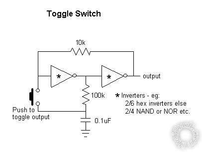
And there is still the previous "Toggle Switch" using inverters which could control a relay of either polarity.
It should be easy to add a pulse- or switch-off (from a brake switch) since a hex inverter IC will have 4 unused inverters and quad NOR or NAND ICs will have 2 spare gates, but I haven't worried about that for lack of response.
And yes - the +V and GND power connections to <whatever> gates (inverting, NAND, NOR) are not shown, but they are usually pins #14 and #7 on hex inverters and quad-gate Integrated Circuits.
(We should be using an 8-pin PIC - so much easier circuit-wise!)
Page of 2

  Printable version Printable version Post ReplyPost New Topic
You cannot post new topics in this forum
You cannot reply to topics in this forum
You cannot delete your posts in this forum
You cannot edit your posts in this forum
You cannot create polls in this forum
You cannot vote in polls in this forum

  •  
Search the12volt.com
Follow the12volt.com Follow the12volt.com on Facebook
Thursday, April 18, 2024 • Copyright © 1999-2024 the12volt.com, All Rights Reserved Privacy Policy & Use of Cookies
Disclaimer: *All information on this site ( the12volt.com ) is provided "as is" without any warranty of any kind, either expressed or implied, including but not limited to fitness for a particular use. Any user assumes the entire risk as to the accuracy and use of this information. Please verify all wire colors and diagrams before applying any information.

Secured by Sectigo
the12volt.com spacer
Support the12volt.com
Top
the12volt.com spacer