
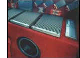
Car Audio / Passive Crossovers, Low Pass, Bandpass, Highpass Filters
 With the use of passive crossovers,
you can drive a woofer, midbass, midrange, and tweeter or more in parallel on each
channel of an amplifier and maintain a safe load (impedance level) on the amplifier
across the entire frequency range.
Each of these loudspeakers receive a particular range of frequencies determined
by one of three crossover filters:
low pass,
high pass, and
band pass.
With the use of passive crossovers,
you can drive a woofer, midbass, midrange, and tweeter or more in parallel on each
channel of an amplifier and maintain a safe load (impedance level) on the amplifier
across the entire frequency range.
Each of these loudspeakers receive a particular range of frequencies determined
by one of three crossover filters:
low pass,
high pass, and
band pass.
The components for these consist of coils and capacitors.
The value of coils and capacitors are selected by the desired crossover
frequency, which is determined by the efficient operating range of the loudspeaker,
the desired slope (rate of cuttoff per octave), and the frequency at which the crossover
components develop a particular impedance or resistance value in relationship to the
loudspeaker's impedance or resistance value. The values of coils and/or capacitors
used for a particular crossover frequency for a 4 ohm loudspeaker will not be
the same for a loudspeaker with a different impedance.
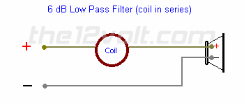
Low Pass Filters
 Low Pass Filters
 |
Low Pass
filters allow low frequencies to pass below a selected crossover
frequency, filtering out all frequencies above it. In a first order (6dB per octave)
filter, this consist of a coil in series with a loudspeaker. Just below the crossover frequency,
the coil begins to add resistance to the circuit. At the crossover frequency enough
resistance has been added to equal the resistance of the loudspeaker and reduce the power by 3 dB
or 50 %. One octave above the crossover frequency, power has been reduced by 6 dB or 75%.
Each octave higher reduces the power by an additional 6 dB. The size of the coil will be
determined by the impedance of the loudspeaker(s) and the desired crossover point. The larger
the size or amount of inductance (millihenries, mHy) is, not physical size, the lower the low
pass frequency will be.
 |
|
|
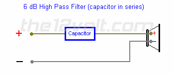
High Pass Filters
|
High Pass Filters |
High Pass filters allow high frequencies above a selected crossover
frequency to pass, filtering out all frequencies below it. In a first order (6dB per octave)
filter, this consist of a capacitor in series with a loudspeaker. Just above the crossover frequency,
the capacitor begins to add resistance to the circuit. At the crossover frequency enough
resistance has been added to equal the resistance of the loudspeaker and reduce the power
by 3 dB or 50 %. One octave below the crossover frequency, power has been reduced by
6 dB or 75%. Each octave lower reduces the power by an additional 6 dB. The size of the
capacitor will be determined by the impedance of the loudspeaker(s) and the desired crossover point.
The smaller the size or value of a capacitor (microfarads, µfd or mfd) is, not physical size,
the higher the high pass frequency will be.
 |
|
|
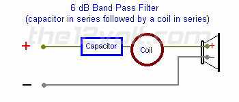
Band Pass Filters
|
Band Pass Filters |
Band Pass filters allow a range of frequencies to pass above a selected
crossover frequency and below another selected crossover frequency, filtering out all
frequencies outside this band. In a first order (6dB per octave) filter,
this consist of a low pass filter (coil) and a high pass
filter (capacitor) in series with a loudspeaker.
Narrow Band Pass Filters are to be used when the bandwidth
is less than two decades.
 |
|
|
Narrow Band Pass Filters
|
Narrow Band Pass Filters |
Narrow Band Pass filters are commonly used with mid-bass
loudspeakers. These allow a narrow band of frequencies to pass. The
bandwidth is considered to be narrow when the low pass frequency is less
than 10 to 20 times the high pass frequency ("less than 1 or 2 decades").
Different formulas apply to selecting coils and capacitors for a narrow band pass
filter. These formulas
should be used if the low pass frequency is less
than 20 times the high pass frequency, if not, distortion will be evident.
Impedance rise occurs more often in midrange loudspeakers (usually at the upper
frequency range of the loudspeaker). Most of the time the rise is well beyond the crossover
frequency and is not necessary to limit the high frequencies to it. If a
Zobel is not used,
only use a high pass filter and not a band pass filter. |
|
|
Zobel Filters
|
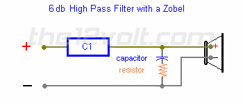
Zobel |
A Zobel is a filter used to stabilized loudspeaker impedance in a
crossover-speaker circuit. This consists of a capacitor with a value equal
to one which gives a crossover frequency at the frequency where the impedance
has doubled, in series with a resistor which has a value equal to 1.25 times
the nominal loudspeaker impedance. This is connected parallel to the loudspeaker between the
loudspeaker and crossover. Zobel Calculator
Loudspeaker manufacturers usually provide you with technical data
containing an impedance curve and other information such as recommended
enclosure sizes, etc. |
|
|
Acoustical Output & Power
|
Acoustical Output & Power |
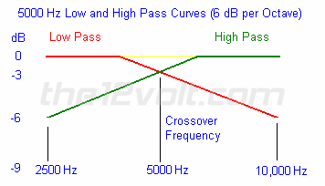
Whenever two loudspeakers are playing the same
frequencies in phase, in the same location, there will be up to a 3 dB rise
in the acoustical output. When crossovers are used, both the low pass filtered
loudspeaker and the high pass filtered loudspeaker are down by 3 dB at the crossover
frequency. Their combined output will be up to 3 dB higher at the crossover point.
The net result is neither a rise or fall in resistance to the amplifer or acoustical output at the
crossover frequency as indicated by the yellow line between the low pass and high pass curves.
This means if both loudspeakers are 4 ohm, the amplifier will see a 4 ohm load below, at, and
above the crossover frequency (*excluding the natural impedance curves of the loudspeakers).
An amplifier rated at an output of 100 watts per channel into a 4 ohm load
will produce 50 watts per channel into an 8 ohm load, and only 25 watts into
a 16 ohm load. The same amplifier will also produce 200 watts per channel into
a 2 ohm load if the amplifier is capable of full output at a 2 ohm load. The crossover
not only separates the frequency ranges for the different loudspeakers in a speaker
system, but also separates these frequency ranges and impedance (resistance) ranges
for the amplifier. |
| An Amplifier Rated at 100
Watts per Channel at 4 ohms which is Capable of Full Output at a 1 Ohm Load per Channel |
| Load | Watts per Channel | % of Power at 4 ohms | dB change |
| 1 ohm | 400 | 400% | +6 |
| 2 ohms | 200 | 200% | +3 |
| 4 ohms | 100 | 100% | 0 |
| 8 ohms | 50 | down 50% | -3 |
| 16 ohms | 25 | down 75% | -6 |
| 32 ohms | 12.5 | down 87.5% | -9 |
| 64 ohms | 6.25 | down 93.75% | -12 |
| 128 ohms | 3.125 | down 96.875% | -15 |
| 256 ohms | 1.5625 | down 98.4475% | -18 |
| 512 ohms | 0.78125 | down 99.21875% | -21 |
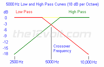
In some cases it is necessary to increase the cut off rate or slope to higher than 6 dB
per octave (first order). With tweeters this is especially important. Low frequencies will damage
tweeters. Using a second order (12 dB per octave) or third order (18 dB per octave) high pass
filter will reduce the lower frequencies at a steeper rate than a first order filter. A tweeter with
a third order high pass filter with a crossover frequency of 5000 Hz
driven by the 100 watt amplifier used in the
power chart above, will recieve about 1.6 watts at 2500 Hz
versus 25 watts with a first order filter at full output. The use of higher order filters allows
loudspeakers to be played at the limits of their efficiency. Higher order filters can also be beneficial
in compensating for natural peaks within the listening enviroment (vehicle).
Different orders may be used in your design. You can have a first order low pass
filter for a woofer, a third order narrow band pass filter for a mid-bass,
a second order band pass filter for a midrange, and a third order high pass filter
for a tweeter.
When building passive crossovers, be sure to calculate for the correct impedance
of each loudspeaker. Impedance is relative to frequency. |
|
|

Follow the12volt.com
 Friday, May 8, 2026
• Copyright © 1999-2026 the12volt.com, All Rights Reserved
• Privacy Policy & Use of Cookies
Friday, May 8, 2026
• Copyright © 1999-2026 the12volt.com, All Rights Reserved
• Privacy Policy & Use of Cookies
Disclaimer:
*All information on this site ( the12volt.com ) is provided "as is" without any warranty of any kind, either expressed or implied, including but not limited to fitness for a particular use. Any user assumes the entire risk as to the accuracy and use of this information. Please
verify all wire colors and diagrams before applying any information.


