Car Security and Convenience / Alarm Sensors and Triggers
Single Stage Sensors
 Single Stage Sensors
 |
| Common 3 Wire |
Many aftermarket electronic sensors, including but not limited to, impact, glass, radar, etc.,
have only three wires to connect if they don't plug directly into the alarm itself. Others
including dual stage sensors do have more , but this will relate to most of them.
- Connect the ground wire to a clean and solid chassis ground.
- Connect the power wire to a constant (+) 12 VDC source.
- Third, connect the (-) output of the sensor to an available (-) inuput of the alarm. If
all inputs are in use by other triggers, use diodes to connect more than one device /
trigger to one input of the alarm as shown above.
Note: if you are installing any type of vibration or glass breakage detector with a remote
start you will need to bypass the output of this sensor while the vehicle is running by
remote. If the remote start does not have an on board relay for this, connect the output
wire of the sensor(s) to terminal #87a of an SPDT relay and connect terminal #30 to the
input of the alarm. Connect the "(-) sensor bypass output" of the remote start to terminal
#85, and connect terminal #86 to a constant (+) 12 VDC source. |
|
|
Dual Stage Sensors
|
Dual Stage Sensors |
| Proprietary |
|
As with many 3 wire electronic sensors, most proprietary dual stage sensors plug directly
into the alarms. If not, each installation will vary depending on the sensor and alarm. You
should first read the manuals that come with each of these. |
| Possible Solution |
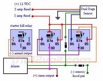
If your manuals were of no help, you may want to try this if the alarm does not have a
pre-warn input or a port to plug the sensor into it, and these inputs and outputs correspond
to the components you are installing as shown below.
Please note this will not work with all alarms and dual stage sensors. Some sensors will
not supply enough current to energize the coil of a relay. Some may not have an output that
is long enough nor an adjustment to control the duration of the output. Pay close attention
to the placement of the diodes.
 |
|
|
Door Triggers / Pin Switches
|
Door Triggers / Pin Switches |
| Door Triggers |
Pin switches rarely need to be added to protect the doors of a vehicle. But when they do,
try installing a factory switch instead of an aftermarket one on the vehicles that have a preexisting hole.
The time saved is usually worth the added cost of the switch.
On some vehicles, tying into the door triggers is as simple as connecting to the wire
of the dome lamp that changes from (+) 12 VDC to ground, or vice-versa on Fords, when any door is opened.
However, some vehicles have a dome lamp delay and/or an auto off feature. On many of these, you will
want to locate the trigger wire(s) that will show either ground or (+) 12VDC when each door is opened, that is
not affected by the dome lamp being on or off.
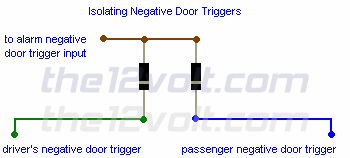
On the vehicles that have two separate (-) door triggers that are isolated
from each other, most commonly found on newer GM vehicles, you will need to use
two 1 amp blocking diodes for all doors to trigger
the alarm.. One trigger is for the
driver's door and the second is for the rest of the doors. If you were just to connect
to one of these and not both, one or more doors of the vehicle would not
be protected by the alarm. If you were to tie each of these together without the blocking
diodes, some features of the vehicle will no longer function properly. Below is an
example of connecting them to one alarm trigger.
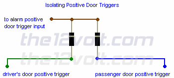
If you need to isolate two (+) positive door triggers,
simply reverse the position of the blocking diodes, facing the anode sides
towards the door triggers and the cathode sides towards the alarm.
This diagram would also apply to connecting the (-) outputs of two
sensors, such as a glass mic and an impact sensor, to one input of
an alarm.
|
| Hood Pins |
|
For hood pins, stay away from any area that will be exposed to water. This may be the easiest place
to mount it many times, but is definitly the worst place to do so. Instead use a bracket that can be mounted to
the firewall or some other solid and dry location. The same would obviously apply to installing pin switches
in the trunk. Don't forget to ground the base of the switch when mounting to a non grounded part of the
vehicle. |
|
|

Follow the12volt.com
 Friday, May 8, 2026
• Copyright © 1999-2026 the12volt.com, All Rights Reserved
• Privacy Policy & Use of Cookies
Friday, May 8, 2026
• Copyright © 1999-2026 the12volt.com, All Rights Reserved
• Privacy Policy & Use of Cookies
Disclaimer:
*All information on this site ( the12volt.com ) is provided "as is" without any warranty of any kind, either expressed or implied, including but not limited to fitness for a particular use. Any user assumes the entire risk as to the accuracy and use of this information. Please
verify all wire colors and diagrams before applying any information.