
Relays / Illuminated Entry & Light Flash Relay Diagrams
Illuminated Entry & Light Flash
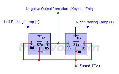
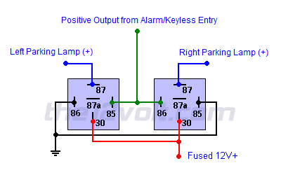
• Illuminated Entry for Vehicles with Positive Door Triggers• Illuminated Entry for Vehicles with Negative Door Triggers
• Basic Light Flash
• Two Wire Light Flash (weak negative output)
• Two Wire Light Flash (strong negative output)
• Two Wire Light Flash (on board relay, positive output)
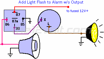
• Adding Light Flash with Siren Output
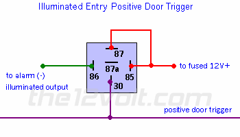
Illuminated Entry for Vehicles with Positive Door Triggers
|
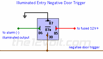
Illuminated Entry for Vehicles with Negative Door Triggers
|
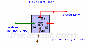
Basic Light Flash
|
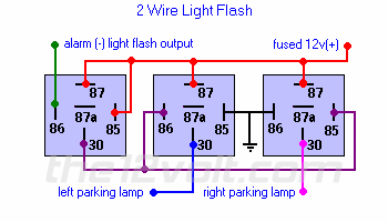
Two Wire Light Flash (weak negative output)
|
Two Wire Light Flash (strong negative output)
|
Two Wire Light Flash (on board relay, positive output)
|
Adding Light Flash with Siren Output
|
Relays and Relay Wiring Diagrams:
• SPDT and SPST Relays
• Converting Polarity
• Door Locks
• Illuminated Entry & Light Flash
• Special Applications
• Starter Interrupts
• Relay Diagrams - Quick Reference
• Relay Forum
• SPDT and SPST Relays
• Converting Polarity
• Door Locks
• Illuminated Entry & Light Flash
• Special Applications
• Starter Interrupts
• Relay Diagrams - Quick Reference
• Relay Forum
Mobile Electronics Basics:
• Diodes
• Glossary of Terms and Definitions
• Ohm's Law
• Recommended Books & DVD's
• Recommended Wire Sizes
• Relays
• Resistors
• Tools and Equipment
• Diodes
• Glossary of Terms and Definitions
• Ohm's Law
• Recommended Books & DVD's
• Recommended Wire Sizes
• Relays
• Resistors
• Tools and Equipment
Car Security and Convenience:
• Basic Connections (inputs)
• Basic Connections (outputs)
• Car Alarm Modules
• Car Alarm Sensors / Triggers
• Door Locks
• Light Flash / Illuminated Entry
• Starter Interrupts
• Accessories & Add-ons
• Basic Connections (inputs)
• Basic Connections (outputs)
• Car Alarm Modules
• Car Alarm Sensors / Triggers
• Door Locks
• Light Flash / Illuminated Entry
• Starter Interrupts
• Accessories & Add-ons

| Search the12volt.com |
Follow the12volt.com 
Monday, February 16, 2026 • Copyright © 1999-2026 the12volt.com, All Rights Reserved • Privacy Policy & Use of Cookies


Monday, February 16, 2026 • Copyright © 1999-2026 the12volt.com, All Rights Reserved • Privacy Policy & Use of Cookies
Disclaimer:
*All information on this site ( the12volt.com ) is provided "as is" without any warranty of any kind, either expressed or implied, including but not limited to fitness for a particular use. Any user assumes the entire risk as to the accuracy and use of this information. Please
verify all wire colors and diagrams before applying any information.


