I am installing the Easyguard EC002-NS PKE Passive Keyless Entry on a friends F250. I used the list
posted here.
I'd previously installed it on two Sequoias and one Tundra without any issue - but I suspect the door (un)lock system is different on the Ford. On my Toyotas, all I had to do was apply positive pulse to one pin to unlock, and positive pulse to another pin to lock.
However, on the F250, I cannot wrap my head around the mechanism.
Power Lock Gray/Yellow - Door Lock Switch in driver door, 4 pin plug, pin 1 or black 8 pin plug, pin 7
Power Unlock Violet/Gray - Door Lock Switch in driver door, 4 pin plug, pin 3 or black 8 pin plug, pin 8
Lock Motor Gray/Brown Reverse Driver Kick --or-- BCM in passenger kick, 36 pin plug (C), pin 35
Driver Unlock Motor Blue/Green Reverse Driver Kick --or-- BCM in passenger kick, 36 pin plug (C), pin 27
Passenger Unlock Motor Brown/Green Reverse BCM in passenger kick, 36 pin plug (C), pin 32
I did 100% of the installation from the BCM. The friend has a service manual for the truck so I was able to confidently find the correct plugs, pins, and colored wires.
My attempt was to connect o the lock motor (Plug C, pin 35), and the passenger unlock motor (Plug C, pin 32). Before applying the alarm, I tried to measure the voltage at each pin to ground. Unfortunately, my meter is too slow to pick up the voltage as the factory (un)lock buttons are pushed.
I think my confusion comes from the "REVERSE" polarity description. Could someone with a bigger brain explain to me how I should attach the Easyguard system? I can configure the outputs to be either positive or negative. There are NO/NC outputs as well, so I should be able to configure it as required. Just need some hand holding.
Thanks!
Well, having heard nothing here, and having found nothing else anywhere on the internet, I attempted to use the reverse polarity (positive pulse) configuration recommended in the manual.
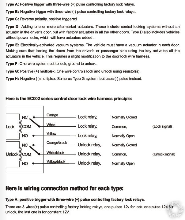
It looks like this:
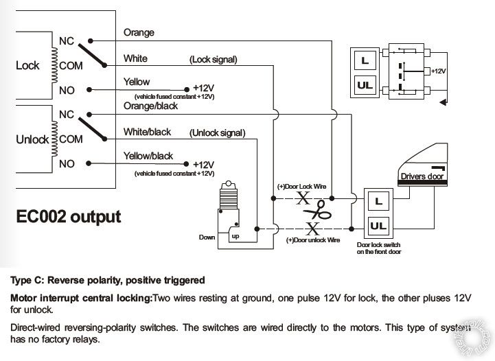
That involved cutting both the lock and unlock wires coming off the BCM. I then connected the common relay output from the alarm (white to lock, white/black to unlock) to the cut wires going to the corresponding cut wires going away from the BCM (presumably going to the actuators). I took the normally closed relay output from the alarm (orange to lock, orange/black to unlock) to the cut wires going back to the BCM.
Now, when alarm harness is disconnected, none of the door lock buttons on the door or key fob work. When the harness is connected and the relays are connected, the OEM buttons work. Just as I expected. However, the lock/unlock function of the alarm (by way of alarm keyfob) does not activate the locks. I can hear the alarms internal relays operating, can see the appropriate 12v+ pulse at the corresponding BCM wire.
I consider myself reasonably proficient with electronics, so this has me incredibly frustrated. My friend is also over the project and wants to just pull the whole system and go back to stock... I can do that but I don't want to give up if I'm missing something stupidly simple.
The truck is equipped with a door module that communicates via CAN Bus. Now...moving on from that.
Disregard the 5 wire setup.
Tie Yellow and Yellow/Black to Ground.
Connect the White wire from the PKE system to the trucks Gray/Yellow wire inside the driver side door.
Connect the White/Black wire from the PKE system to the trucks Violet/Gray wire inside the driver side door.
This setup allows the vehicles door lock switches to still function without any extra leg work.