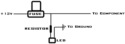
Hello everyone,it's been a long time since i last posted,Jeff from Velocity has allways helped me with stuff.Anyway i'm about to redoo my system in my car so in order to minimize the stuff on the rack i would like to put the fuse blocks out of sight,but i would like to be able to know if they are OK without unscrewing panels off so LED's came to mind.I could run leds to the LED's that take much less space (i run a multy-component system so i have a lot of fuses to hook up).Can somebody design a sort of diagram (i know i have to use resistors wired in paralel...right ?, to step down the voltage ,unless there are 12 V LED's).I know that there are LED's out there that are dual color (GREEN/ red) so i could easy tell if one of the fuses burned ...
Thank you

Here's your formula. Noone can give you an exact answer since there are so many variations of LED's out there.
R = (Source Voltage - LED voltage required) / (current in milliamps) * 1000
So say you have a 3.6v led that needs 30mA, and we'll assume your car charges to about 13.5v with the car running.
R = (13.5v - 3.6v) / (30) * 1000
R = (9.9 / 30) * 1000
R = .33 * 1000
R = 330 ohm resistor needed in SERIES.
You'd want to use a 1/2 watt or 1/4 watt resistor depending on what led your using. There's your formula just plugin your LED specs and see what you come up with..Luckily LED's are very tolerant so you don't have to get them dead on or anything just close enough will be fine. Then just put the LED's in parallel off the component side of your fuses and your good to go. Only problem then is that they are on your main power fuses which have constant voltage meaning your LED's are on all the time even when the car is off. What you could do then is tie all of your LED's negative sides together and run them through a switch, with ground on the other side so you can turn them on and off..Or use a relay off of your remote turn on wire like so:
85 to your remote turn on wire
86 to ground
30 to ground
87 to your LED's negative side (cathode)
87a unused
Using this method LED on means the fuse is good. LED off means the fuse is bad. Dual color LED's would take a little bit more work to setup not sure if you want to go through that. Hope that helps,
Mike

Hi Mike,thank you for the detailed diagram you just gave me (and others),and yes i think just one color LED is good enough,dual color would be nice but i think it will complicate things a bit.
Thank you again and much apreciated.
Dan

Hey there, I had this same question about 2 months ago and I have done what you want and it works wonderful. Go to my thread
Fuse Block LED's
If you are wanting to use dual color LED's, it works great. Use the 3rd diagram and you should have no problems. If you have any questions, ask away. xetmes is who drew up the diagram, so if you have any questions, he can also help you.
Great instructions mj239air,this is exactly what i was looking for,i apreciate all the help and instructions.I have been hanging around this forum for over one year and this is one the most educated forums i have found.BTW does anyone know what Jeff from Velocity Motorsports is up to ?,is he the moderator here ?...this guy is absolutely amaizing,please let me know if anyone knows heis whereabouts.
Peace and thank you all.
Dan

Also thank you xetmes too,you sure know your stuff,much apreciated.
Dan

wow i remeber that thread... If you build this take a picture i always like to see what transpires from these diagrams. Good luck, and no problem for the diagrams

yea ill post that, I built this circuit to allow a toggle with a push button switch, but i learned (from people here) they make latching relays that will toggle which is a better idea...


