picking the relay i need
Printed From: the12volt.com
Forum Name: Car Security and Convenience
Forum Discription: Car Alarms, Keyless Entries, Remote Starters, Immobilizer Bypasses, Sensors, Door Locks, Window Modules, Heated Mirrors, Heated Seats, etc.
URL: https://www.the12volt.com/installbay/forum_posts.asp?tid=110908
Printed Date: May 06, 2026 at 5:21 AM
Topic: picking the relay i need
Posted By: phree_refill
Subject: picking the relay i need
Date Posted: January 23, 2009 at 8:53 AM
Hello all. I am looking for a mechanical latching relay exactly like the one shown in the diagram listed on this site ( https://www.the12volt.com/relays/page5.asp#sppbdl ). I finally found a webiste that looks pretty promissing as far as selling one that I need because they have over 300 different latching relays listed on their site. My problem now is that I don't know which one of these relays they have lsited is what I need. I don't know much about reading the numbers and what-not listed in the desription areas for relays to know if I'm buying the one that I need. If anyone could help me pick out one that is exaclty like, or very similar to, the mechanical latching relay I referenced earlier I would be very very grateful. Here is a link to the site where I have found all these latching relays https://www.alliedelec.com/Search/SearchResults.aspx?Ntk=Primary&Ntt=latching+relay&No=0&N=0&sid=11F02970FFF8 Thanks in advance!
Replies:
Posted By: loneranger
Date Posted: January 23, 2009 at 9:32 AM
What application will this be used for?
-------------
Ideal - cmon dude, add to topics in a useful manner, not stuff that is obvious.
Story - Phzzzt! Hey, what happened?! ... Isn't it obvious?
Moral - Never dismiss the obvious.
Posted By: phree_refill
Date Posted: January 23, 2009 at 10:19 AM
Well I installed a remote starter on my truck. It has all the bells and whistles. It has a dedicated trunk release wire. I plan to install a tailgate lock on my truck. I'm making one with some aftermarket door lock actuators that I bought on ebay. Rather than wiring the actuators into my power door locks, I want to hook them up to that truck release wire. The trunk release wire only sends out one momentary negative pulse. I need two distinguished negative pulses in order to lock and unlock the actuators. The diagram that I listed above is exactly what I need and would be perect. So when I push the trunk button on my remote once it will unlock the actuator, and then when I push the trunk button a second time it will lock the actuator. I already have the other relays wired to make my actuators function properly. I just need to split the impulse from that trunk wire and have the two fire alternativley in regards to each other.
Posted By: loneranger
Date Posted: January 23, 2009 at 10:24 AM
How will you know if it is locked or unlocked, at any given time? I ask because there may be a more secure design flowchart, if you think about it.
-------------
Ideal - cmon dude, add to topics in a useful manner, not stuff that is obvious.
Story - Phzzzt! Hey, what happened?! ... Isn't it obvious?
Moral - Never dismiss the obvious.
Posted By: phree_refill
Date Posted: January 23, 2009 at 11:24 AM
To know when it is locked or unlockled I plan to drill a small hole in the trim that goes around my tailgate handle and it will serve as a little window to a small flat slide that I am going to attach to the actuator. The little slide will have two colors; red and green. red will be on one half and green on the other. The small flat slide will move back and forth with the movement of the actuator. When it is unlocked you will be able to see the green part of the slide through the window and when it's locked you will see the red part. It should stay locked until I push the trunk release button again. I have no worries about the trunk release button being accidentally pushed and hence accidentally locking or unlocking the tailgate because in order to activate the trunk release impulse you have to hold the door unlock button down for 4 seconds. I doubt it will ever be accidentally depressed for 4 seconds straight. The remote starter unit I have BTW is the Design-Tech Ready Remote Deluxe #23927
Posted By: loneranger
Date Posted: January 23, 2009 at 11:55 AM
Let me find another source for a supplier. ------------- Ideal - cmon dude, add to topics in a useful manner, not stuff that is obvious.
Story - Phzzzt! Hey, what happened?! ... Isn't it obvious?
Moral - Never dismiss the obvious.
Posted By: phree_refill
Date Posted: January 23, 2009 at 12:07 PM
Awesome! Hey thanks so much! You have no idea how frustrating its been to find one of these things.
Posted By: ckeeler
Date Posted: January 23, 2009 at 7:23 PM
phree_refill wrote:
Hello all. I am looking for a mechanical latching relay exactly like the one shown in the diagram listed on this site ( https://www.the12volt.com/relays/page5.asp#sppbdl ). I finally found a webiste that looks pretty promissing as far as selling one that I need because they have over 300 different latching relays listed on their site. My problem now is that I don't know which one of these relays they have lsited is what I need. I don't know much about reading the numbers and what-not listed in the desription areas for relays to know if I'm buying the one that I need. If anyone could help me pick out one that is exaclty like, or very similar to, the mechanical latching relay I referenced earlier I would be very very grateful. Here is a link to the site where I have found all these latching relays https://www.alliedelec.com/Search/SearchResults.aspx?Ntk=Primary&Ntt=latching+relay&No=0&N=0&sid=11F02970FFF8 Thanks in advance!
hmmm......funny ive never seen this diagram before. and i'd like to know how it would work because i dont think it can. ive never seen a latching relay that works like that. a single coil latching relay works by energizing the coil and then the load contacts become latched. another pulse on one of the coil contacts cant unlatch it. in order to unlatch, the coil has to be energized in the opposite polarity it was energized with to latch it and then it will unlatch. sorta like how alot of alarm units will have low current door lock outputs that flip-flop polarity. the coil polarity on one of these has to be flip-flopped back and forth to make the load contacts latch and release. of course there are dual coil latching relays.....but those have 3 pins to activate the coils. a center pin for a common and then two outside pins. the outside pins recieve a pulse of the opposite polarity of the center pin to make the load contacts release or latch depending on which pin was pulsed activating its corresponding coil. below is a diagram of what im trying to say. 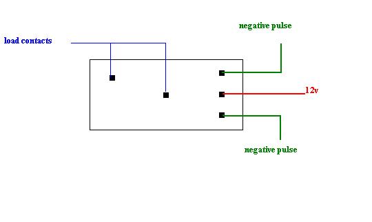
with 12v on the center pin, if you pulse one of the outer pins with a negative pulse the contacts will latch until the opposite outside pin is pulsed with a negative, unlatching the contacts until the opposite pin that unlatched the relay is pulsed again, which in turn will latch the contacts once more. and again as i stated before......a single coil latching relay has to have the polarity reversed back and forth to latch and unlatch. so......my question is.....how does that diagram work? is there a single coil latching relay that does what the one in the diagram is described as doing? if so I sure would like to have the part number for that relay. ?? anybody?.....all you old schoolers?....moderators?....the12volt? i would like to know where i can get one of those relays too.
Posted By: i am an idiot
Date Posted: January 23, 2009 at 9:06 PM
The relay in the picture works like a retractable ball point ink pen. Press the top and it pushes the pen out. Press the top again and it retracts the pen. The relay works the same way.
Posted By: ckeeler
Date Posted: January 23, 2009 at 9:14 PM
i understand thats what the diagram says it does. heres the problem.....i've never seen a relay like that, and dont think it exists, so.......whats the part number? where can i find one? if its out there i'd like to have about a dozen or so.(seriously)
Posted By: i am an idiot
Date Posted: January 23, 2009 at 9:34 PM
Posted By: ckeeler
Date Posted: January 23, 2009 at 10:02 PM
hmmm....am i missing something? am i nuts? help me here. IAAI, did you read the data sheet? thats a DS1E-ML-DC12v. well....thats a 1 form c relay......it says right on the data sheet, and i quote "energize with reverse polarity to transfer the contacts" ??? thats just what i was saying earlier about single coil latching relays.
Posted By: i am an idiot
Date Posted: January 24, 2009 at 4:41 AM
Posted By: ckeeler
Date Posted: January 24, 2009 at 5:45 AM
i guess a guy could just use one side and forget the other contacts  . i still dont get that original diagram, that would NEVER work with the relay pictured.........oh well(sigh)
Posted By: loneranger
Date Posted: January 24, 2009 at 12:11 PM
ckeeler wrote:
i guess a guy could just use one side and forget the other contacts. i still dont get that original diagram, that would NEVER work with the relay pictured.........oh well(sigh)
You are correct. The relays provided in this thread are spring loaded with no ratchet. The relay diagram provided on the site is spring loaded with a ratchet. The ratchet is what makes the relay work with a single, same polarity pulse. I'm sure you can imagine that working. The relays provided in this thread will work on reverse lock/unlock outputs, like those on DEI systems. In other words, hook the lock/unlock outputs to the coil. What you should be looking for, based on the diagram on the site, is a ratcheting relay. - Here is a mechanical ratcheting relay.
- Here is a SSD(electronic) ratcheting relay but, it will produce the exact same results.
So in essence, mechanically the relay pictured on the site is a ratcheting relay, not latching. ------------- Ideal - cmon dude, add to topics in a useful manner, not stuff that is obvious.
Story - Phzzzt! Hey, what happened?! ... Isn't it obvious?
Moral - Never dismiss the obvious.
Posted By: ckeeler
Date Posted: January 24, 2009 at 12:25 PM
i think ive mentioned that several times already on this thread ranger. i know how the relay on that diagram is supposed to work....thats not what im asking about, thats not what my question is, a chimp could see thats what the relay in the diagram is supposed to do.......however im positive that relay doesnt work like that. so........my question is "what is the part number for the pictured relay??" can anybody out there give an answer to that question? i'd really like to have some of those that are the SAME type as that pictured and also operate as described. i cant find it. anyone???
Posted By: ckeeler
Date Posted: January 24, 2009 at 1:29 PM
well.....regardless the 0047 electronic relay will work great. ill use that instead. thank you ranger!
Posted By: phree_refill
Date Posted: February 02, 2009 at 5:23 PM
Is there any way i can wire up a series of relays in order to get the same effect as the ratcheting relay i mentioned in my first post? I've tried to come up with how to wire up some relays but i just can't wrap my mind around it. Anyone that is good with utilizing relays then this would be a challenge for you. I need to take one momentary negative pulse and split it into two momentary negative pulses AND have them only fire alternatively. So when i push the trunk release button and it fires one negative pulse, one time it needs to give me a negative pulse down one wire but not the other and then the next time i push the trunk release button i need it to fire down the oposite wire but not the original one.
Posted By: i am an idiot
Date Posted: February 02, 2009 at 6:18 PM
Posted By: KPierson
Date Posted: February 02, 2009 at 6:26 PM
i am an idiot wrote:
You would have to use a great deal of care with that system - if you leave any of the relays latched while the car isn't running it will drain the battery. Are you dead set on staying with a relay only setup? It may be beneficial to use an electronic solution. ------------- Kevin Pierson
Posted By: i am an idiot
Date Posted: February 02, 2009 at 6:54 PM
I forgot to mention that you will need to run the output of the above setup to a fifth relay to give you the result you are looking for. 12 V + output to 86 of the fifth relay. Ground 85. 30 goes to the wire that has ground when you push trunk release button. 87A to one wire and 87 to the other wire. The state of the fifth relay will determine which of the 2 wires will see the ground that is going to be on 30. As Kevin stated, in an energized state, a relay will draw about 160 milliamps each. One relay staying engaged can run a battery down in a day or so. 4 or 5 of them, will be worse.
Posted By: ckeeler
Date Posted: February 02, 2009 at 7:47 PM
KPierson wrote:
You would have to use a great deal of care with that system - if you leave any of the relays latched while the car isn't running it will drain the battery.Are you dead set on staying with a relay only setup? It may be beneficial to use an electronic solution.
so true. not only that, think of the cost involved with that many relays as well as the size. the 0047 electronic relay would be cheaper, or you could build your own electronic solution for less and the space and size would be worth it by far.
Posted By: phree_refill
Date Posted: February 03, 2009 at 5:55 AM
So how could i go about an electronic route? At this point I am not real concerned on using primarily just relays but any combination of devices are acceptable. it doesn't have to be anything fancy. Whatever i can rig up that requires the fewest parts/ space and/or is easiest to wire and cheap. Or any combination of those qualities would be fantastic.
Posted By: phree_refill
Date Posted: February 05, 2009 at 8:55 AM
I would just give in and buy that 0047 relay but their website doesn't have any place to order it. Has anyone tried ordering it over the phone?
Posted By: KPierson
Date Posted: February 05, 2009 at 12:21 PM
I would do it with either a microcontroller or a flip flop. Unfortunately both are going to require a bit of circuity. The microcontroller is nice because you don't need any calculations or debounce circuitry - you can use general interface circuits and do all the timing in the software. The drawback here is most microcontrollers are 5vdc so you'll need a power supply circuit. A flip flop can generally be ran at 12vdc so you won't need a power supply, but you'll need to build a debounce interface that may require you to make some calculations and test some things out to make sure you get rid of all the bounce. Both solutions will leave you with "memory" that doesn't involve latching a relay so your standby current will be extremely low. ------------- Kevin Pierson
Posted By: dualsport
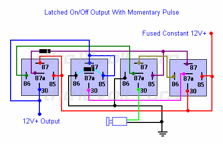
Date Posted: March 24, 2009 at 1:22 AM
Drew this up a couple years ago, this uses a J-K FF like Kevin mentioned. Considerably cheaper, a dollar in parts and some assembly time. 
Posted By: dualsport
Date Posted: March 24, 2009 at 1:24 AM
This was the original thread on it
Posted By: theviperman
Date Posted: March 31, 2009 at 10:20 AM
Another item you can use is the TR-7 module - it does exactly what you want it to do. You give it a single pulsed ground and it will provide either constant power or ground (depending on which wire you use.) Give it the same pulsed ground (you can also give a pulsed positive signal) and it will turn the output off. I use the TR-7 to bypass the ECU on my Stratus to power the fog lights with the factory momentary switch independent of the headlights or highbeams. Search for "PAC TR-7" on google and you'll find it easily. It's kinda pricey - over $30, shipped. But it does 7 different functions, is programmable, and can be reprogrammed for other uses. Jeff ------------- Don't mind me...
Posted By: jdub765
Date Posted: April 03, 2009 at 8:28 PM
I've been searching for the same exact thing!! What I'm going to do is use a 4027 IC chip and a relay.
The 4027 chip is a dual JK flip flop. If you use just one of the flip flops, and set J and K to high, then the output to Q will toggle back and forth with each high pulse into the clock input. So you'd attach your button to the clock input for one of the flip flops.
https://info.hobbyengineering.com/specs/Fairchild-CD4027BC.pdf
|