the12volt.com spacer
icon

part for latching relay or equivalent


Post ReplyPost New Topic
< Prev Topic Next Topic >
cahilj 
Member - Posts: 11
Member spacespace
Joined: February 21, 2008
Posted: February 27, 2008 at 11:30 AM / IP Logged  

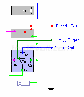
I have a keyless entry number pad that has a timed NO output (either + or -, whichever is needed). It also has a NC output, which opens when the code is typed in (basically terminals 30, 87 and 87a of a SPDT relay, and the coil is operated by the keypad). I have reversing polarity door locks, so I need two outputs. I would like to build this-

part for latching relay or equivalent -- posted image.

I can't seem to find a single coil latching relay with a 12vdc coil, or anything that has pins similar to the one shown.

Does anyone have a good part number? Or can I do something else instead? Do I even need a latching relay considering what the keypad will do? I have a DEI 611t, but I don't think it will do what I want. Thanks.

Ween 
Platinum - Posts: 1,366
Platinum spacespace
Joined: August 01, 2004
Location: Illinois, United States
Posted: February 27, 2008 at 9:31 PM / IP Logged  

hi,

you may want to look into a DEI 452T door lock pulse generator.  it will convert a latched input (such as a ground while armed) to door lock and unlock pulses.  you can use those outputs to drive relays to operate your door locks.

mark

cahilj 
Member - Posts: 11
Member spacespace
Joined: February 21, 2008
Posted: February 28, 2008 at 10:51 AM / IP Logged  

Hmmm....

I don't think the 452T will do what I want either. It needs a constant input. Once the keypad de-energizes the coil, the output will open and the 452T will unlock the doors. The keypad itself isn't latching, its only momentary, and the timed output can only be set for a maximum of 99 secs.

dualsport 
Silver - Posts: 983
Silver spacespace
Joined: September 27, 2005
Location: United States
Posted: March 03, 2008 at 10:46 PM / IP Logged  
These are single coil latching relays,
1 Form C, 2 Form C, and 4 Form C respectively:
DS1E-ML-DC12V DS2E-ML-DC12V DS4E-ML-DC12V
Available from Digikey: $5.44
dualsport 
Silver - Posts: 983
Silver spacespace
Joined: September 27, 2005
Location: United States
Posted: March 03, 2008 at 10:51 PM / IP Logged  
Also keep in mind these aren't rated for very high current, so depending on what you're planning on switching with these, you may need more parts or circuitry. I'm not clear on what you're going to hook it up to from the description.
cahilj 
Member - Posts: 11
Member spacespace
Joined: February 21, 2008
Posted: March 06, 2008 at 7:59 PM / IP Logged  
Excellent. I plan on building the circuit I pictured above using the keypad as the switched ground. I'm going to use it to control the door locks on the truck, as well as 3 solenoids for compartment locks on the truck. I'm going to add a relay to each output to handle the actual load. I plan on putting both the latching relay and another PCB SPDT non-latching relay (as opposed to a Bosch style relay) on a board in a project box behind the keypad. So, both the latching and non latching in the box won't see any load other than the coils for the Bosch style relays outside the box. If all that makes sense.....
dualsport 
Silver - Posts: 983
Silver spacespace
Joined: September 27, 2005
Location: United States
Posted: March 06, 2008 at 8:24 PM / IP Logged  
The latching relay works by reversing the polarity to the coil to either set or reset it, so you'll need to work out a way to do that. Your diagram above looks like you were expecting it to toggle with each pulse input, which it won't do. Even if it did, you may have some timing problems when the bottom relay switches state, after the latching one toggles. It would probably issue a short pulse on the other line before you get the one you wanted, which may or may not be a problem.
It'd probably be easier using solid state devices to do this rather than a mechanical relay, if that's something you'd be inclined to try.
cahilj 
Member - Posts: 11
Member spacespace
Joined: February 21, 2008
Posted: March 09, 2008 at 8:45 PM / IP Logged  

Hmmm... now I'm a bit confused. I was under the impression that the diagram was good for what I wanted. I pulled it right from here- https://www.the12volt.com/relays/page5.asp. As far as I can tell, when the switch is pressed, the coil on the latcher is engergized, which will then in turn energize the coil on the large relay, sending ground to output 2. When the switch is released, both coils de-energize and no output is active. Now that the latcher is latched to the output, when the switch is pressed again, the latcher coil will energize, unlatching the output, and the big relay will output to output 1, since its coil isn't energized. When the switch is released, the latcher will de-energize and no output will be active.

Isn't that how a mechanical latching relay works? It maintains the last state it was in until the coil is energized again? part for latching relay or equivalent -- posted image. 

part for latching relay or equivalent -- posted image.

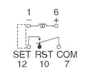
This is the diagram for the part number you provided. As far as I can tell, pin 1 would get the switched ground, pins 6 and 7 would get 12v+, and pin 12 would connect to terminal 86. So you're saying the polarity between 1 and 6 would need to reverse to unlatch it? I guess my understanding of latching relays is less than what I thought....part for latching relay or equivalent -- posted image.

dualsport 
Silver - Posts: 983
Silver spacespace
Joined: September 27, 2005
Location: United States
Posted: March 10, 2008 at 8:28 AM / IP Logged  
In the description below the 1 coil latching relay, it reads
Diagram shows the “reset” position when terminals 1
and 6 are energized.
Energize with reverse polarity to transfer contacts.
So if you applied a second pulse of the same polarity it wouldn't switch states, but remain latched in the same position-
cahilj 
Member - Posts: 11
Member spacespace
Joined: February 21, 2008
Posted: March 19, 2008 at 4:01 PM / IP Logged  
So how does the first diagram I posted actually work? It doesn't? Or are there latching relays that will latch and unlatch with the same pulse?
Page of 3

  Printable version Printable version Post ReplyPost New Topic
You cannot post new topics in this forum
You cannot reply to topics in this forum
You cannot delete your posts in this forum
You cannot edit your posts in this forum
You cannot create polls in this forum
You cannot vote in polls in this forum

  •  
Search the12volt.com
Follow the12volt.com Follow the12volt.com on Facebook
Thursday, May 16, 2024 • Copyright © 1999-2024 the12volt.com, All Rights Reserved Privacy Policy & Use of Cookies
Disclaimer: *All information on this site ( the12volt.com ) is provided "as is" without any warranty of any kind, either expressed or implied, including but not limited to fitness for a particular use. Any user assumes the entire risk as to the accuracy and use of this information. Please verify all wire colors and diagrams before applying any information.

Secured by Sectigo
the12volt.com spacer
Support the12volt.com
Top
the12volt.com spacer