part for latching relay or equivalent
Printed From: the12volt.com
Forum Name: Relays
Forum Discription: Relay Diagrams, SPDT Relays, SPST Relays, DPDT Relays, Latching Relays, etc.
URL: https://www.the12volt.com/installbay/forum_posts.asp?tid=102594
Printed Date: April 02, 2026 at 3:36 AM
Topic: part for latching relay or equivalent
Posted By: cahilj
Subject: part for latching relay or equivalent
Date Posted: February 27, 2008 at 11:30 AM
I have a keyless entry number pad that has a timed NO output (either + or -, whichever is needed). It also has a NC output, which opens when the code is typed in (basically terminals 30, 87 and 87a of a SPDT relay, and the coil is operated by the keypad). I have reversing polarity door locks, so I need two outputs. I would like to build this- 
I can't seem to find a single coil latching relay with a 12vdc coil, or anything that has pins similar to the one shown. Does anyone have a good part number? Or can I do something else instead? Do I even need a latching relay considering what the keypad will do? I have a DEI 611t, but I don't think it will do what I want. Thanks.
Replies:
Posted By: Ween
Date Posted: February 27, 2008 at 9:31 PM
hi, you may want to look into a DEI 452T door lock pulse generator. it will convert a latched input (such as a ground while armed) to door lock and unlock pulses. you can use those outputs to drive relays to operate your door locks. mark
Posted By: cahilj
Date Posted: February 28, 2008 at 10:51 AM
Hmmm.... I don't think the 452T will do what I want either. It needs a constant input. Once the keypad de-energizes the coil, the output will open and the 452T will unlock the doors. The keypad itself isn't latching, its only momentary, and the timed output can only be set for a maximum of 99 secs.
Posted By: dualsport
Date Posted: March 03, 2008 at 10:46 PM
These are single coil latching relays,
1 Form C, 2 Form C, and 4 Form C respectively:
DS1E-ML-DC12V DS2E-ML-DC12V DS4E-ML-DC12V
Available from Digikey: $5.44
Posted By: dualsport
Date Posted: March 03, 2008 at 10:51 PM
Also keep in mind these aren't rated for very high current, so depending on what you're planning on switching with these, you may need more parts or circuitry. I'm not clear on what you're going to hook it up to from the description.
Posted By: cahilj
Date Posted: March 06, 2008 at 7:59 PM
Excellent. I plan on building the circuit I pictured above using the keypad as the switched ground. I'm going to use it to control the door locks on the truck, as well as 3 solenoids for compartment locks on the truck. I'm going to add a relay to each output to handle the actual load. I plan on putting both the latching relay and another PCB SPDT non-latching relay (as opposed to a Bosch style relay) on a board in a project box behind the keypad. So, both the latching and non latching in the box won't see any load other than the coils for the Bosch style relays outside the box. If all that makes sense.....
Posted By: dualsport
Date Posted: March 06, 2008 at 8:24 PM
The latching relay works by reversing the polarity to the coil to either set or reset it, so you'll need to work out a way to do that. Your diagram above looks like you were expecting it to toggle with each pulse input, which it won't do. Even if it did, you may have some timing problems when the bottom relay switches state, after the latching one toggles. It would probably issue a short pulse on the other line before you get the one you wanted, which may or may not be a problem.
It'd probably be easier using solid state devices to do this rather than a mechanical relay, if that's something you'd be inclined to try.
Posted By: cahilj
Date Posted: March 09, 2008 at 8:45 PM
Hmmm... now I'm a bit confused. I was under the impression that the diagram was good for what I wanted. I pulled it right from here- https://www.the12volt.com/relays/page5.asp. As far as I can tell, when the switch is pressed, the coil on the latcher is engergized, which will then in turn energize the coil on the large relay, sending ground to output 2. When the switch is released, both coils de-energize and no output is active. Now that the latcher is latched to the output, when the switch is pressed again, the latcher coil will energize, unlatching the output, and the big relay will output to output 1, since its coil isn't energized. When the switch is released, the latcher will de-energize and no output will be active. Isn't that how a mechanical latching relay works? It maintains the last state it was in until the coil is energized again?  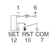
This is the diagram for the part number you provided. As far as I can tell, pin 1 would get the switched ground, pins 6 and 7 would get 12v+, and pin 12 would connect to terminal 86. So you're saying the polarity between 1 and 6 would need to reverse to unlatch it? I guess my understanding of latching relays is less than what I thought....
Posted By: dualsport
Date Posted: March 10, 2008 at 8:28 AM
In the description below the 1 coil latching relay, it reads
Diagram shows the âresetâ position when terminals 1
and 6 are energized.
Energize with reverse polarity to transfer contacts.
So if you applied a second pulse of the same polarity it wouldn't switch states, but remain latched in the same position-
Posted By: cahilj
Date Posted: March 19, 2008 at 4:01 PM
So how does the first diagram I posted actually work? It doesn't? Or are there latching relays that will latch and unlatch with the same pulse?
Posted By: dualsport
Date Posted: March 20, 2008 at 12:21 AM
From the description in the diagram is looks like the relay is able to mechanically latch and unlatch with successive pulses. Most likely there is something available to do that, maybe working like a ball point pen mechanism. Unfortunately, the one I linked to won't do that though, sorry to point you in the wrong direction there.
Whoever drew up the diagram probably can tell you the part number for that relay though, must be someone here-
Even with the correct relay though, the output may not be as clean as you might need, because it'll briefly send a short pulse on the other output before clicking over to the second output. If that's a problem, or you can't locate the relay, it'd be easier to do it with solid state components. A J-K flip flop along with a logic gate would do it.
Posted By: dreamert
Date Posted: March 27, 2008 at 3:18 PM
dualsport wrote:
These are single coil latching relays,
1 Form C, 2 Form C, and 4 Form C respectively:
DS1E-ML-DC12V DS2E-ML-DC12V DS4E-ML-DC12V
Available from Digikey: $5.44
I was wondering, how can I find the same exact relays but in a more 'automotive oriented' packaging, I mean with a connector socket and all, not SPDT type ? Any idea what to look for on the DigiKey site ?
Posted By: cahilj
Date Posted: March 27, 2008 at 8:04 PM
dualsport wrote:
Even with the correct relay though, the output may not be as clean as you might need, because it'll briefly send a short pulse on the other output before clicking over to the second output. If that's a problem, or you can't locate the relay, it'd be easier to do it with solid state components. A J-K flip flop along with a logic gate would do it.
In that case, since I have even less clue about solid state stuff , and I just spent about 15 minutes Googling solid state flip flops with no idea what I'm looking at or for, do you have any good links to get what I need? Or maybe a diagram?
Posted By: dualsport
Date Posted: March 27, 2008 at 9:12 PM
Posted By: dualsport
Date Posted: March 28, 2008 at 8:28 AM
Arggh. I see D2 is upside down in the diagram in that post I made. Should be like this instead- 
Posted By: jigc
Date Posted: March 30, 2008 at 8:58 AM
cahilj wrote:
guys,
i've been looking for this impulse relay (mechanical latched) for years and yet to find it.
i need this 2 negative output to lock/unlock the door with momentary switch.
from what i understand from this schematic:
1. when momentary switch is hit#1
2. armature of impulse relay is closed
3. coil relay (85-86) is stayed neutral (due to same voltage)
4. 1st output is shorted to ground via 87a-30-momentary switch
5. door is locked
--------
1. when momentary switch is hit#2
2. current flow from impulse relay armature (due to close) to ground via 86-85-momentary swith
3. coil relay is energized and close its armature (87-30)
4. current flows from coil of impulse relay and open its armature
5. 2nd output is shorted to ground via 87-30-memontary switch
5. door is unlocked
could anyone advice me on the alternative??
regards
jigc
Posted By: dualsport
Date Posted: March 30, 2008 at 10:06 AM
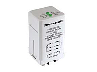
magnecraft
This one should operate as required for that setup-
711 Impulse Sequencing Relay / DPDT 12 Amp Rating
The 711 Impulse Sequencing relay is an alternating relay used for load sharing or toggling ON/OFF of the load. Uni-directional momentary pulses cause the contacts to transfer from one side to the other. There is no need to redirect the polarity of the input in order to change and maintain states.
$23.20 at allied here
Posted By: dualsport
Date Posted: March 30, 2008 at 10:45 AM
Not sure how the LED indication atop the relay is wired in; couldn't find out the details from what I saw on the manufacturer's datasheet. It only says the LEDs indicate which side the contacts are in, but not much else.
edit: the LEDs are only lit up when the input pulse is coming in, so it won't draw any power at all in the standby state.
Posted By: jigc
Date Posted: March 31, 2008 at 12:01 AM
hi dualsport, thanx for the reply. yes, i think 711 can be used. my problem are: it is not common here (allied does not ship internationally), cant find at ebay, and little overkill with DPDT based on original schematic, i only need SPST. if this is too hard to get, i'm thinking of electronic circuit for the solution. how is your circuit above to be modified for this application? regards
Posted By: dualsport
Date Posted: March 31, 2008 at 12:28 AM
The difference is that you want a momentary pulse output instead of the steady toggled output, so you could just use a logic gate like an AND, (or NAND) taking the pulse input, combined with one of the outputs from the flip flop (the Q or /Q).
That way the output only goes active during the time you send the input pulse, and is low otherwise.
If you use a NAND gate, you can run the output to a transistor as shown in the upper dotted box. When the input switch and Q are both high, the gate output goes low, which turns on the transistor and outputs 12V. You could use that signal directly or drive a relay if necessary. A relay would be necessary if you need to switch higher current or voltages.
Add miscellaneous protection circuitry and you should have an equivalent function.
Posted By: cahilj
Date Posted: April 08, 2008 at 8:41 PM
dualsport- Thanks for all the help you've given. I'm going to give this a shot and see if I can package it to fit on the board I have.
|