the12volt.com spacer
icon

latching relay


Post ReplyPost New Topic
< Prev Topic Next Topic >
sub95 
Member - Posts: 6
Member spacespace
Joined: January 30, 2007
Location: United States
Posted: January 31, 2007 at 5:11 PM / IP Logged  

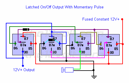
Hi, I am trying to get a neg pulse to stay constant 12+ but also turn off with the neg pulse, i found this pic but dont understand what looks to me is a  push button on off?.

And where would i put the neg input to turn relays on/off..

Thanks

sub95 
Member - Posts: 6
Member spacespace
Joined: January 30, 2007
Location: United States
Posted: January 31, 2007 at 9:30 PM / IP Logged  
Here is the pic i was talking about, 
latching relay -- posted image.
sub95 
Member - Posts: 6
Member spacespace
Joined: January 30, 2007
Location: United States
Posted: February 02, 2007 at 10:56 AM / IP Logged  

Hi, i looked and tried to make the latched on/off output with momentary pulse with Diodes. using Diodes1N4001, this is a single neg pulse button i am using to activate relays.

But when i tried doing this i had to leave the #1 relay #87A unhooked to turn on the light, then i had to touch 87A to the other side of it which is #3 relay 85 and #4 relay # 87, it sounds like it un latches one of the relays when i do this? now i push the key pad light turns off?  Anyone know why this is? i followed the diagram to a tee.

Thanks

hotwaterwizard 
Silver - Posts: 1,350
Silver spacespace
Joined: December 11, 2003
Location: California, United States
Posted: February 08, 2007 at 10:11 PM / IP Logged  
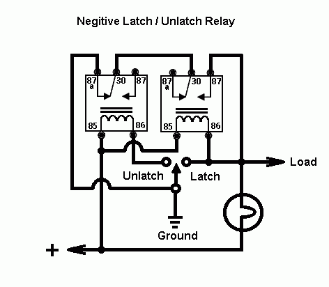
latching relay -- posted image.
John DeRosa (Hotwaterwizard)
Stockton California
When in doubt, try it out !
hotwaterwizard 
Silver - Posts: 1,350
Silver spacespace
Joined: December 11, 2003
Location: California, United States
Posted: February 08, 2007 at 10:34 PM / IP Logged  

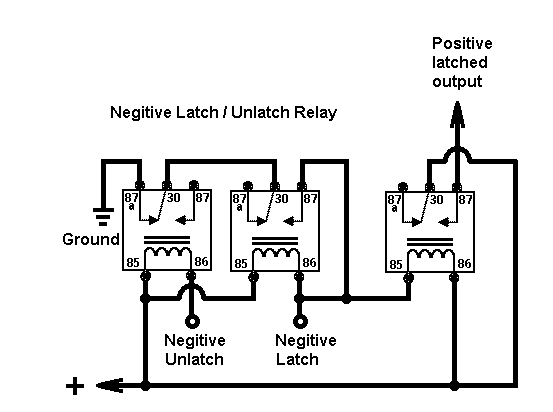
Add an extra relay and here is what you get.

latching relay -- posted image.

John DeRosa (Hotwaterwizard)
Stockton California
When in doubt, try it out !
dualsport 
Silver - Posts: 983
Silver spacespace
Joined: September 27, 2005
Location: United States
Posted: February 17, 2007 at 10:33 AM / IP Logged  
Not sure what your application is, but if you need this to control something that's going to be on all the time while on battery power, you might be better off using solid state circuitry to do it. If this is for something that's AC powered, then the drain from the relays won't be a concern.
hotwaterwizard 
Silver - Posts: 1,350
Silver spacespace
Joined: December 11, 2003
Location: California, United States
Posted: February 17, 2007 at 8:13 PM / IP Logged  
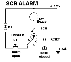
latching relay -- posted image.
John DeRosa (Hotwaterwizard)
Stockton California
When in doubt, try it out !
dualsport 
Silver - Posts: 983
Silver spacespace
Joined: September 27, 2005
Location: United States
Posted: February 18, 2007 at 11:48 AM / IP Logged  
Try this to get a toggling output from a single pulse input-
If your input pulse isn't clean and free from glitches, it may be necessary to add some filtering to the input to keep it from toggling multiple times on the single pulse.
You can use different output stages depending on what you need to drive with it; those two transistors should be limited to a half amp or less.
Each time the input is pulsed, the U1A Q output should toggle between 0V and 12V. Since that output can supply only a relatively small amount of current, that line is used to turn the transistors in the dotted boxes on/off, which can handle more current. Which one you use depends on whether you want a ground switch output or a 12V output. Just use larger transistors if you need more drive current.
The D1 and D2 are just to help protect the chip input in case the drive signal has spikes on it; if it's a clean input, they aren't needed. If you're driving relays with the transistors, it'd be good to add suppression diodes to protect them from the turn off spike.
latching relay -- posted image.

Sorry, you can NOT post a reply.
This topic is closed.

  Printable version Printable version Post ReplyPost New Topic
You cannot post new topics in this forum
You cannot reply to topics in this forum
You cannot delete your posts in this forum
You cannot edit your posts in this forum
You cannot create polls in this forum
You cannot vote in polls in this forum

  •  
Search the12volt.com
Follow the12volt.com Follow the12volt.com on Facebook
Tuesday, May 14, 2024 • Copyright © 1999-2024 the12volt.com, All Rights Reserved Privacy Policy & Use of Cookies
Disclaimer: *All information on this site ( the12volt.com ) is provided "as is" without any warranty of any kind, either expressed or implied, including but not limited to fitness for a particular use. Any user assumes the entire risk as to the accuracy and use of this information. Please verify all wire colors and diagrams before applying any information.

Secured by Sectigo
the12volt.com spacer
Support the12volt.com
Top
the12volt.com spacer