the12volt.com spacer
icon

part for latching relay or equivalent


Post ReplyPost New Topic
< Prev Topic Next Topic >
dualsport 
Silver - Posts: 983
Silver spacespace
Joined: September 27, 2005
Location: United States
Posted: March 20, 2008 at 12:21 AM / IP Logged  
From the description in the diagram is looks like the relay is able to mechanically latch and unlatch with successive pulses. Most likely there is something available to do that, maybe working like a ball point pen mechanism. Unfortunately, the one I linked to won't do that though, sorry to point you in the wrong direction there.
Whoever drew up the diagram probably can tell you the part number for that relay though, must be someone here-
Even with the correct relay though, the output may not be as clean as you might need, because it'll briefly send a short pulse on the other output before clicking over to the second output. If that's a problem, or you can't locate the relay, it'd be easier to do it with solid state components. A J-K flip flop along with a logic gate would do it.
dreamert 
Member - Posts: 1
Member spacespace
Joined: March 27, 2008
Location: Quebec, Canada
Posted: March 27, 2008 at 3:18 PM / IP Logged  

dualsport wrote:
These are single coil latching relays,
1 Form C, 2 Form C, and 4 Form C respectively:
DS1E-ML-DC12V DS2E-ML-DC12V DS4E-ML-DC12V
Available from Digikey: $5.44

I was wondering, how can I find the same exact relays but in a more 'automotive oriented' packaging, I mean with a connector socket and all, not SPDT type ?

Any idea what to look for on the DigiKey site ?

cahilj 
Member - Posts: 11
Member spacespace
Joined: February 21, 2008
Posted: March 27, 2008 at 8:04 PM / IP Logged  

dualsport wrote:
Even with the correct relay though, the output may not be as clean as you might need, because it'll briefly send a short pulse on the other output before clicking over to the second output. If that's a problem, or you can't locate the relay, it'd be easier to do it with solid state components. A J-K flip flop along with a logic gate would do it.

In that case, since I have even less clue about solid state stuff part for latching relay or equivalent - Page 2 -- posted image., and I just spent about 15 minutes Googling solid state flip flops with no idea what I'm looking at or for, do you have any good links to get what I need? Or maybe a diagram?

dualsport 
Silver - Posts: 983
Silver spacespace
Joined: September 27, 2005
Location: United States
Posted: March 27, 2008 at 9:12 PM / IP Logged  
dualsport 
Silver - Posts: 983
Silver spacespace
Joined: September 27, 2005
Location: United States
Posted: March 28, 2008 at 8:28 AM / IP Logged  
Arggh. I see D2 is upside down in the diagram in that post I made.
Should be like this instead-
part for latching relay or equivalent - Page 2 -- posted image.
jigc 
Member - Posts: 2
Member spacespace
Joined: August 14, 2005
Location: Liberia
Posted: March 30, 2008 at 8:58 AM / IP Logged  
cahilj wrote:
part for latching relay or equivalent - Page 2 -- posted image.
guys,
i've been looking for this impulse relay (mechanical latched) for years and yet to find it.
i need this 2 negative output to lock/unlock the door with momentary switch.
from what i understand from this schematic:
1. when momentary switch is hit#1
2. armature of impulse relay is closed
3. coil relay (85-86) is stayed neutral (due to same voltage)
4. 1st output is shorted to ground via 87a-30-momentary switch
5. door is locked
--------
1. when momentary switch is hit#2
2. current flow from impulse relay armature (due to close) to ground via 86-85-momentary swith
3. coil relay is energized and close its armature (87-30)
4. current flows from coil of impulse relay and open its armature
5. 2nd output is shorted to ground via 87-30-memontary switch
5. door is unlocked
could anyone advice me on the alternative??
regards
jigc
dualsport 
Silver - Posts: 983
Silver spacespace
Joined: September 27, 2005
Location: United States
Posted: March 30, 2008 at 10:06 AM / IP Logged  
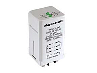
magnecraft
This one should operate as required for that setup-
     711 Impulse Sequencing Relay / DPDT 12 Amp Rating
The 711 Impulse Sequencing relay is an alternating relay used for load sharing or toggling ON/OFF of the load. Uni-directional momentary pulses cause the contacts to transfer from one side to the other. There is no need to redirect the polarity of the input in order to change and maintain states.
part for latching relay or equivalent - Page 2 -- posted image.
$23.20 at allied here
dualsport 
Silver - Posts: 983
Silver spacespace
Joined: September 27, 2005
Location: United States
Posted: March 30, 2008 at 10:45 AM / IP Logged  
Not sure how the LED indication atop the relay is wired in; couldn't find out the details from what I saw on the manufacturer's datasheet. It only says the LEDs indicate which side the contacts are in, but not much else.
edit: the LEDs are only lit up when the input pulse is coming in, so it won't draw any power at all in the standby state.
jigc 
Member - Posts: 2
Member spacespace
Joined: August 14, 2005
Location: Liberia
Posted: March 31, 2008 at 12:01 AM / IP Logged  

hi dualsport,

thanx for the reply.

yes,  i think 711 can be used.

my problem are:  it is not common here (allied does not ship internationally), cant find at ebay, and little overkill with DPDTpart for latching relay or equivalent - Page 2 -- posted image.

based on original schematic, i only need SPST.

if this is too hard to get, i'm thinking of electronic circuit for the solution.

how is your circuit above to be modified for this application?

regards

dualsport 
Silver - Posts: 983
Silver spacespace
Joined: September 27, 2005
Location: United States
Posted: March 31, 2008 at 12:28 AM / IP Logged  
The difference is that you want a momentary pulse output instead of the steady toggled output, so you could just use a logic gate like an AND, (or NAND) taking the pulse input, combined with one of the outputs from the flip flop (the Q or /Q).
That way the output only goes active during the time you send the input pulse, and is low otherwise.
If you use a NAND gate, you can run the output to a transistor as shown in the upper dotted box. When the input switch and Q are both high, the gate output goes low, which turns on the transistor and outputs 12V. You could use that signal directly or drive a relay if necessary. A relay would be necessary if you need to switch higher current or voltages.
Add miscellaneous protection circuitry and you should have an equivalent function.
Page of 3

  Printable version Printable version Post ReplyPost New Topic
You cannot post new topics in this forum
You cannot reply to topics in this forum
You cannot delete your posts in this forum
You cannot edit your posts in this forum
You cannot create polls in this forum
You cannot vote in polls in this forum

  •  
Search the12volt.com
Follow the12volt.com Follow the12volt.com on Facebook
Monday, May 20, 2024 • Copyright © 1999-2024 the12volt.com, All Rights Reserved Privacy Policy & Use of Cookies
Disclaimer: *All information on this site ( the12volt.com ) is provided "as is" without any warranty of any kind, either expressed or implied, including but not limited to fitness for a particular use. Any user assumes the entire risk as to the accuracy and use of this information. Please verify all wire colors and diagrams before applying any information.

Secured by Sectigo
the12volt.com spacer
Support the12volt.com
Top
the12volt.com spacer