keyless entry issue for 93 rx7
Printed From: the12volt.com
Forum Name: Car Security and Convenience
Forum Discription: Car Alarms, Keyless Entries, Remote Starters, Immobilizer Bypasses, Sensors, Door Locks, Window Modules, Heated Mirrors, Heated Seats, etc.
URL: https://www.the12volt.com/installbay/forum_posts.asp?tid=111052
Printed Date: April 03, 2026 at 12:19 PM
Topic: keyless entry issue for 93 rx7
Posted By: rotarypower101
Subject: keyless entry issue for 93 rx7
Date Posted: January 27, 2009 at 4:17 PM
Hi guys looking for some help on a door lock triggering circuit for a 1993 Mazda RX7 for keyless entry.
Is thee a trigger circuit out there that is smart enough to deal with this stock system? What are the search terms that I should be using to research this type of setup?
The issues that I am running into is that , I cannot seem to find a way of triggering the stock system electronically to take the pulse commands from a audiovox car alarm.
it appears from the Lock Actuator Scematic for this car that the circuit must charge off the current state the lock position is in and then it can throw the actuator, ie simply grounding out G/R or G/Y to B on the door lock switch LH does not work.
What must be done to make the circuit work is G/R must be held to B (allowing it to charge) and then G/R must be released from B and then immediately switched to G/Y & B or vise versa to make the circuit operate in the desired manner from a locked state to an unlocked state.
Anyone have some ideas or info to lead me in the right direction?
 [/QUOTE]
Replies:
Posted By: ckeeler
Date Posted: January 27, 2009 at 5:22 PM
ahhh..... the old rotory powered Mazda. it's fun to call autozones and checker parts stores and ask for a set of pistons and piston rings. ha! have you considered adding an actuator in the drivers door? thats normaly how its done.
Posted By: BNLUIS
Date Posted: January 27, 2009 at 5:30 PM
X2 , actuator in door , have fun  ------------- Luis
Sound Waves
Is up to the installer to test all wires with a DMM whenever possible.
Posted By: rotarypower101
Date Posted: January 27, 2009 at 6:12 PM
ah yes, I should have mentioned (didnt expect people would have been so familiar with the inner workings of this particular vehicle) I actually purchased a RHD actuator overseas that fits right into the system and works flawlessly when patched into the passenger side of the USDM system. I have used it for years with the sock system, but am adding keyless entry, and this issue has now popped up.
For posterity, using a standard generic door actuator would indeed fix the issue because there is a switch internally that is actuated manually by the door locking mechanism But this is not a very desirable way to actuate the door locking mechanism, as the area most use to actuate the manual locking mechanism is very weak, and failures have occurred because of the thin plastics that must be used when you shoehorn in a actuator in that cramped little space. Some even resort to trimming the housings of the actuator in certain cases. So this is not a very durable solution, and I would like to approach it in a different manner if possible.
My approach was to find a perfectly fitting stock actuator, and while using this stock actuator did introduce an undesired side effect that would have been otherwise omitted by using a generic actuator, I am fairly confident there is a way around the issues that the stock mazda circuit presents.
Does anyone have some ideas on how actuating the stock actuator in the schematic could be accomplished?
Thanks for taking the time to look over the problem, also can anyone that understands these things better than I explain what this circuit that charges a cap and then releases to drive a actuator would even be called so that I may search for answers here and elsewhere for solutions to this issue?
Posted By: ckeeler
Date Posted: January 28, 2009 at 10:55 AM
rotarypower101 wrote:
What must be done to make the circuit work is G/R must be held to B (allowing it to charge) and then G/R must be released from B and then immediately switched to G/Y & B or vise versa to make the circuit operate in the desired manner from a locked state to an unlocked state.
Anyone have some ideas or info to lead me in the right direction?
OK, i have an idea. a couple of the guys and I were discussing a certain type of relay in a couple other threads. links are below so you can read them. but basicly i was looking for a relay to do a specific job. all i could find is actually the type of relay you need to make your locks work, only instead of a SPST, you will need a SPDT. easy enough. read these threads, and if your interested in making it work, ill get you the part number and draw the diagram. https://www.the12volt.com/installbay/forum_posts.asp?tid=110908&KW=ckeeler&tpn=1 https://www.the12volt.com/installbay/forum_posts.asp?tid=110908&KW=ckeeler&tpn=1
Posted By: rotarypower101
Date Posted: January 28, 2009 at 10:17 PM
WOW
.. deshavu!
Single momentary pulse to toggle on/off
ckeeler wrote:
i understand thats what the diagram says it does. heres the problem.....i've never seen a relay like that, and dont think it exists, so.......whats the part number? where can i find one? if its out there i'd like to have about a dozen or so.(seriously)
rotarypower101 wrote:
I have asked and specified to my supplier that I need a relay that will LOCK into position and stay until the next momentary pulse, but I was told that this is not made, is this true?
I also asked if there is a relay that existed that would fit into that circuit, and would fit that particular need for functionality. Still nothing
AFAIK there exists no relay that will do as described for this circuit; secondly there is no latching relay that will change the coils polarity. While it still could exist, I looked and asked around fairly thoroughly, as well as searched the web, and found no particular part numbers that could be ordered or used to track down a part that could be used in substitution.
I unsuccessfully built this design, making necessary adjustments with micro switches after the original diagram failed to operate in the desired fashion, NO DICE! Just got wild oscillations of the relay.
I asked a lot of people how to make this simple circuit work with this special relay, and all I got from 3 different supply houses was a does not exist reply for what I surmised would have to be a special operation of the relay.
Why this part does not exist as a single component is beyond me though, as it would seem to be a very simple to use and have very desirable functionality.
Anyway, I did end up building the 5 relay option and designing my board for my space constraints, it turned out well, but there is the issue of shock to the system because of the application that could potentially release one of the relays causing the circuit to shut off unintentionally. Thats why I was hoping to use a latching relay as in the first diagram.
I actually did find a correctly working board, which could be tracked down again through my notes, but I unfortunately burnt up the IC when trying to power it with another suggested circuit to reduce 12V to 10V IIRC. Voltage reducer worked great when tested with my MM, but when applied to the board instantly let the smoke out
.
Its a very tricky board and I am sad to have seen it go as if fit my needs perfectly, because it drives the included relay regardless of shock to the system to the proper position.
Details of that particular project can be found here:
seadooproject
Custom_Jim, did have a viable solution, though it did not fit my needs.
Posted By: rotarypower101
Date Posted: January 28, 2009 at 10:22 PM
In the above post I meant to say JDM passenger actuator, installed as a driver side actuator on a USDM car. Just so thee is no confusion.
Posted By: rotarypower101
Date Posted: January 28, 2009 at 10:25 PM
Also ckeele, i am not sure how would this particular momentary pulse would work for the posted circuit I have mentioned above, the circuit needs to charge as opposed to simply supplying a ground to the aforementioned pinouts? of which i have the timer unit didssasemleled if the components used are of any help diagnosing a solution
ckeeler wrote:
rotarypower101 wrote:
What must be done to make the circuit work is G/R must be held to B (allowing it to charge) and then G/R must be released from B and then immediately switched to G/Y & B or vise versa to make the circuit operate in the desired manner from a locked state to an unlocked state.
Anyone have some ideas or info to lead me in the right direction?
OK, i have an idea. a couple of the guys and I were discussing a certain type of relay in a couple other threads. links are below so you can read them. but basicly i was looking for a relay to do a specific job. all i could find is actually the type of relay you need to make your locks work, only instead of a SPST, you will need a SPDT. easy enough. read these threads, and if your interested in making it work, ill get you the part number and draw the diagram.
https://www.the12volt.com/installbay/forum_posts.asp?tid=110908&KW=ckeeler&tpn=1
https://www.the12volt.com/installbay/forum_posts.asp?tid=110908&KW=ckeeler&tpn=1
Posted By: ckeeler
Date Posted: January 29, 2009 at 12:03 AM
ha! its funny that you asked about this a few years back also. yea that relay in that diagram WILL NOT work that way. you can use one though. its goin to be slightly different. you want a dual coil latching relay, and not SPST, you need SPDT. look at the diagram below. 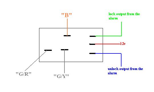
in the thread i referred you to that i posted in, i drew a picture of a dual coil latching relay. it latches the contacts back and forth by pulsing the outer pins. the center goes to constant 12v, the outer ones will be pulsed by the lock outputs from the alarm, which in turn toggles the contacts back and forth. the only difference in this pic and the last one is that this one has an "extra" contact pin (SPDT). how in the world could that not work for you? it does EXACTLY what you say you need. am i missing something? or will this work for you? heres one, and its under $5 https://search.digikey.com/scripts/DkSearch/dksus.dll?Detail&name=PB963-ND
Posted By: chriswallace187
Date Posted: January 29, 2009 at 3:55 AM
Here's a really stupid guess on my part, being that I've never touched a '93-up RX7.
Is there a possibility that the diagram is just wrong as far as the switch(specifically, should it show the lock switch as normally open entirely rather than normally closed with the GREEN/ red unlock)? And that simply connecting the (-) outputs from an aftermarket keyless entry would work the locks properly?
-------------
C Renner's Auto Electronix
My service is cheap, quick, and good - pick any two
Posted By: lanman31337
Date Posted: January 29, 2009 at 6:26 AM
I'm with Chris - it looks like you can pulse the 0 (i'm guessing orange) wire from the actuator with a negative pulse and it should unlock. Also the G (Green?) from the lock with a negative pulse and it would work as well.
Posted By: ckeeler
Date Posted: January 29, 2009 at 8:16 AM
and actually rotorypower, dont let me mislead you. you will need 2 of these relays. you will have to use another relay like the one i showed you to "break" the "B" wire and hold it open in an armed (on lock state) until you unlock closing the "B" wire, allowing the switch to function as normal. the reason being is you cant just use the one relay because what if the switch is resting between "B" and "G/R", and your relay pulses "B" to "G/Y"? so you must you another relay to disconnect "B" from the switch when arming and hold it there while armed so you can trigger the wires form "B" through the other relay. on disarm it would connect "B" back together so you could use the switch as normal. second relay diagram is below. 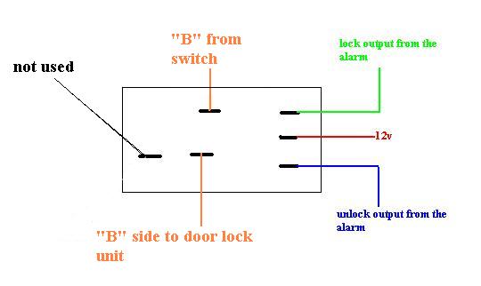
Posted By: rotarypower101
Date Posted: January 29, 2009 at 5:54 PM
OK I think i see where you are going with this now, I will not have time to sufficiently go over the details and see if it will work until Saturday though.
Are you suggesting removing the switch and replacing it with a controllable DPDT relay and this is where the signal from the keyless entry is coming from?
If this is you suggestion I am not sure it will work, because the switch in the diagram is an integral part of the system as it is there to tell all the doors to unlock when a user manually pulls the locking mechanism in the car.
Removing this door lock switch would sacrifice one feature in lieu of another.
However I may be able to piggyback the system without issue, which you might also be suggesting? Y/N?
Posted By: rotarypower101
Date Posted: January 29, 2009 at 5:54 PM
BTW ckeeler thanks for the help and ideas, I really would like to make this work properly, and am stuck until a solution presents itself to be able to finish the rest of my little project.
Also, can you describe in your most elaborate descriptive explanation how this DPTH relay will work if the coil polarity is not toggled upon activation or a push of the momentary switch?
That was the issue I could never overcome.
Posted By: rotarypower101
Date Posted: January 29, 2009 at 6:01 PM
Sorry for the above posts they were in regards to yesterdays postings, as I had not refreshed the page to see the newer current posts.
Posted By: ckeeler
Date Posted: January 29, 2009 at 6:27 PM
rotarypower101 wrote:
I may be able to piggyback the system without issue, which you might also be suggesting? Y/N?
Yes thats what i mean. is it making sense now? with the diagrams and all?
Posted By: rotarypower101
Date Posted: January 29, 2009 at 10:02 PM
I am fairly certain there is no way to simply pulse the actuator, as it is not a solenoid, but a motor that turns axially and twits a matting finger that locks/unlocks the latching mechanism.
chriswallace187 wrote:
Is there a possibility that the diagram is just wrong as far as the switch(specifically, should it show the lock switch as normally open entirely rather than normally closed with the GREEN/ red unlock)? And that simply connecting the (-) outputs from an aftermarket keyless entry would work the locks properly?
Posted By: rotarypower101
Date Posted: January 29, 2009 at 10:18 PM
Hey ckeeler, ya I think what you are saying will probably work, I am going to try and throw something together tonight and see if I cant make it work. Luckily I have some unused latching relays gathering dust from july 06 that just might fit the bill ;)
Posted By: ckeeler
Date Posted: January 29, 2009 at 11:45 PM
ha! yea you probably do huh? in any case i know it will work im certain of it. if you need i can draw up the diagram with both relays and the wires in the car to make it more clear, but you seem like you know the system in this car very well, and i think you get what im showing you (at least i hope so). the switch will still work as normal with this setup and you still be able to do the keyless entry as well. so you'll be good.
Posted By: chriswallace187
Date Posted: January 29, 2009 at 11:55 PM
rotarypower101 wrote:
I am fairly certain there is no way to simply pulse the actuator, as it is not a solenoid, but a motor that turns axially and twits a matting finger that locks/unlocks the latching mechanism.
I know you wouldn't pulse the motor wires, but the switched wires from the manual motion of the actuator should do the trick. Since you've already presumably got it working so that moving either actuator will operate both doors, I think if you send a ground to the respective "lock" and "unlock" switch wires, both doors will operate as you want them to.
The lock timer with its capacitors and such is basically a non-issue. Its purpose is roughly the same as the constant-to-momentary relay that the12volt has shown here:
The factory lock circuit on your RX-7 is more or less the same design. When the actuator is moved to the Locked or Unlocked position, it grounds the GREEN/ YELLOW or GREEN/ Red wire respectively. This in turn activates the respective relay which is integrated into the timer module (you can see the coils and the switching contacts of each relay connected by the dashed line). This is a very common method of switching used by central locking systems(those controlled by movement of the lock itself rather than a separate switch).
Since the grounded GREEN/ YELLOW or GREEN/ Red is connected directly to the relay coil the path of least resistance would be the coil itself, which would send power to the actuator constantly. This is the reason for the capacitors - once they charge(after 0.5-1.0 seconds) the relay cuts out and the actuator stops trying to move any further.
Try applying ground yourself to the GREEN/ YELLOW and GREEN/ Red, and I'm extremely confident it will operate the doorlocks as you want it to without the need for extra relays.
chriswallace187 wrote:
Is there a possibility that the diagram is just wrong as far as the switch(specifically, should it show the lock switch as normally open entirely rather than normally closed with the GREEN/ red unlock)? And that simply connecting the (-) outputs from an aftermarket keyless entry would work the locks properly?
------------- C Renner's Auto Electronix
My service is cheap, quick, and good - pick any two
Posted By: chriswallace187
Date Posted: January 29, 2009 at 11:59 PM
From your original post:
rotarypower101 wrote:
it appears from the Lock Actuator Scematic for this car that the circuit must charge off the current state the lock position is in and then it can throw the actuator, ie simply grounding out G/R or G/Y to B on the door lock switch LH does not work.
This is sort of the reverse of how it actually works. The ground will throw the actuator immediately. The capacitor charging stops it from continuing to do so indefinitely. ------------- C Renner's Auto Electronix
My service is cheap, quick, and good - pick any two
Posted By: rotarypower101
Date Posted: January 30, 2009 at 11:12 PM
I am having a hard time wrapping my head around why this would be so ?
Could you explain the process in a lot more detail please?
Because when grounding out G/R or G/Y to B from a state of G/R ,G/Y and B disconnected from the door lock switch and if any pair or combination of wire are put together nothing happens.
Only when the grounding out of G/R or G/Y to B is held for a definite amount of time and then, and only then can a change to the alternate wire of G/R or G/Y cause a lock/unlock action to take place.
I am not saying that what you are trying to explain is not happening I just dont follow your reasoning behind this statement, and would like clarification of the ideas being presented.
chriswallace187 wrote:
From your original post:
rotarypower101 wrote:
it appears from the Lock Actuator Scematic for this car that the circuit must charge off the current state the lock position is in and then it can throw the actuator, ie simply grounding out G/R or G/Y to B on the door lock switch LH does not work.
This is sort of the reverse of how it actually works. The ground will throw the actuator immediately. The capacitor charging stops it from continuing to do so indefinitely.
Posted By: rotarypower101
Date Posted: January 30, 2009 at 11:17 PM
ckeeler wrote:
i understand thats what the diagram says it does. heres the problem.....i've never seen a relay like that, and dont think it exists, so.......whats the part number? where can i find one? if its out there i'd like to have about a dozen or so.(seriously)
Hey ckeeler, tell me do you find this interesting?
A friend tracked down this little part, and while not as cheap as a do it yourself 4/5 relay option, I believe it fits the bill of a single momentary pulse causing two distinct states.
impulse latching relay
Posted By: rotarypower101
Date Posted: January 30, 2009 at 11:36 PM
rotarypower101 wrote:
Because when grounding out G/R or G/Y to B from a state of G/R ,G/Y and B disconnected from the door lock switch and if any pair or combination of wire are put together nothing happens.
Only when the grounding out of G/R or G/Y to B is held for a definite amount of time and then, and only then can a change to the alternate wire of G/R or G/Y cause a lock/unlock action to take place.
Just want to confirm this is what you are asking me to do correct? and that i am not misinterpreting what is being explained.
Also am i explaining myself sufficiently, am i leaving any ambiguity in my explanations of how the system reacts to physically changing it and empirically observing an outcome?
Posted By: chriswallace187
Date Posted: January 31, 2009 at 12:46 AM
The test you put down is indeed what I was suggesting.
I could be wrong about this, but is it the case that prior to your installation of the 2nd actuator(the RHD one that you put in the driver's door) you would either lock or unlock the driver's door and the passenger's would follow after a delay of 1 second or so? Or is the delay much longer/shorter?
About how long do you have to hold the ground on the G/R or G/Y in order for the locks to operate? If it's less than 3.5 seconds, most Audiovox alarms can be programmed to output a (-) pulse for that duration.
-------------
C Renner's Auto Electronix
My service is cheap, quick, and good - pick any two
Posted By: ckeeler
Date Posted: January 31, 2009 at 11:31 AM
rotarypower101 wrote:
ckeeler wrote:
i understand thats what the diagram says it does. heres the problem.....i've never seen a relay like that, and dont think it exists, so.......whats the part number? where can i find one? if its out there i'd like to have about a dozen or so.(seriously)
Hey ckeeler, tell me do you find this interesting?
A friend tracked down this little part, and while not as cheap as a do it yourself 4/5 relay option, I believe it fits the bill of a single momentary pulse causing two distinct states.
impulse latching relay
thanks but i already found the part i need. interesting your still working on this. i guess i can assume you havent yet tried the relay setup i suggested.
Posted By: rotarypower101
Date Posted: February 01, 2009 at 12:46 PM
ckeeler wrote:
[ i guess i can assume you havent yet tried the relay setup i suggested.
No I dropped the ball a little bit, I thought I had the correct relay on hand turns out I did not after reviewing the part number . But the correct parts have been ordered as well as some other fun parts for 3 other projects. Remote controlled PowerWheel anyone? ;)
But I am 99% confident that it will work now once the correct parts are procured.
As long as the circuit is allows to maintain a latched contact state and simply be remotelyactuated by the alarm while disengaging the stock door switch while this is happening, there really is no way it could not work, save for the small variances from introducing different components into the mix.
Posted By: rotarypower101
Date Posted: February 01, 2009 at 2:05 PM
I know what ckeeler has outlined should work, but I have always been one to not leave well enough alone
so if you will bear with me I would like to try it from both angles if you would be willing to stick with it a little while longer Chris.
Because I am sure there is a way to do it as you are explaining, my only concern is that there might be more to it than simply pulsing G/R or G/Y.
Wouldnt the circuit, the way I have observed it to work, have to charge the opposing cap first then ground the intended lock/unlock wire even if the pulse width was abnormally long?
chriswallace187 wrote:
The test you put down is indeed what I was suggesting.
I could be wrong about this, but is it the case that prior to your installation of the 2nd actuator(the RHD one that you put in the driver's door) you would either lock or unlock the driver's door and the passenger's would follow after a delay of 1 second or so? Or is the delay much longer/shorter?
Correct, I could try to time it with my stopwatch if you are interested to know a rough approximation.
chriswallace187 wrote:
About how long do you have to hold the ground on the G/R or G/Y in order for the locks to operate? If it's less than 3.5 seconds, most Audiovox alarms can be programmed to output a (-) pulse for that duration.
just tested as per your request, holding the ground on the G/R or G/Y takes less than a second to charge the circuit allowing a lock/unlock to take place.
Also toggling between G/R or G/Y to B ( once the circuit has been charged) allows for immediate toggling between a desired state of lock/unlock.
So I guess the concern is, can this alarm reproduce this extra step of acting like it has charged the system first? I know you said it does not work this way, but this is the best way I have to describe my thoughts on the topic. Also I do not see anything in the users manual stating that the pulse width can be increased, how is this acomplished?
Been looking around her for other info Chris, you seem to be very prolific around here on the topics I was searching through!
Thanks for the help, I am very grateful as well as others from the other threads I have been perusing, I am sure.
below are the PDFs for the car alarm and satellite remote start pager if they are at all handy.
audiovox APS 786T PDF manual
CL100 satalite pager
Posted By: chriswallace187
Date Posted: February 01, 2009 at 3:17 PM
By chance do you have the rest of the alarm connected? If so you could try temporarily connecting the red and green lock switch wires to the G/R and G/Y on the vehicle and operating the remote to see if it works the locks.
If the alarm isn't hooked up yet you could just temporarily connect the black wire to ground and the 2 red wires to 12V in order to test the lock outputs. Also plug the antenna in.
I would recommend 2 things for this test - first, do it with the actuator switch connected because you'll actually be operating the system once its working. Second, put diodes inline on the red and green wires, cathode side facing the Audiovox brain. (This is because the outputs are positive as well and you'd directly short them to ground otherwise.)
-------------
C Renner's Auto Electronix
My service is cheap, quick, and good - pick any two
|