icbm7071 alarm in 2004 f150
Printed From: the12volt.com
Forum Name: Car Security and Convenience
Forum Discription: Car Alarms, Keyless Entries, Remote Starters, Immobilizer Bypasses, Sensors, Door Locks, Window Modules, Heated Mirrors, Heated Seats, etc.
URL: https://www.the12volt.com/installbay/forum_posts.asp?tid=133223
Printed Date: April 10, 2026 at 3:43 AM
Topic: icbm7071 alarm in 2004 f150
Posted By: antman1
Subject: icbm7071 alarm in 2004 f150
Date Posted: January 07, 2013 at 5:37 PM
I have a 2004 Ford F150 Heritage and have not found a wiring diagram for this install.
I have purchased the ICBM 7071 and have installed one of these in my other vehicle with the help of the awesome members on this site and was hoping I may be able to get some more help on wiring this up in the F150. I am not sure on what wire will go to what. If anyone can help me I would really appreciate it. Here is the wiring section of the instruction manual for this alarm. Thank you all in advance.
Here is the wiring part of the book:


If you can help please let me know, Thank you.
Replies:
Posted By: kreg357
Date Posted: January 07, 2013 at 6:13 PM
Very easy truck to do. The 2004 thru 2007 F150's are the same. The hardest wires to locate are the
door lock and unlock wires. If you do a search in this forum on this truck you should be rewarded
with a lot of info and even some pictures of the door lock wires in the drivers door sill.
Did you purchase a bypass module yet for the trucks ignition immobilizer system? There are many
bypass modules for this vehicle, but with most you will need two working, non-clone, keys to program
the bypass module to the truck. ( My favorite is the Directed 1100F, available on EBay NIB for under $20.)
For vehicle wiring, here are some sources :
Here is a link to Bulldog Security : https://www.bulldogsecurity.com/bdnew/vehiclewiringdiagrams.asp
Here is a link to Ready Remote : https://www.readyremote.com/main.asp
Here is a link to AudioVox : https://techservices.audiovox.com/AccessRequest.aspx Sign-up & info is free.
Print out the wire guide listings from all available sources, then compare them. There could be differences.
Then make a ICBM 7071 Harness list with Harness / Pin / wire color / wire name to F150 or bypass module
chart. Post that and forum members will be able to advise, update and correct before you do your bench
prep and install. ------------- Soldering is fun!
Posted By: antman1
Date Posted: January 07, 2013 at 6:29 PM
Is this the bypass module you were talking about?
Directed Install Essentials 1100F Ford PATS/Securilock Remote Start Interface
I will try to look over the diagrams and see if I can figure it out. thank you.
Posted By: kreg357
Date Posted: January 07, 2013 at 6:50 PM
Yes, that is the bypass module. It was manufactured by iDatalink for XpressKit and is now discontinued. However, it is an extremely reliable module and very easy to program. Quite a bargain at $15. Just make sure it is New In Box / never used and complete with wire harnesses.
Does the truck have Factory Remote Keyless Entry? ------------- Soldering is fun!
Posted By: antman1
Date Posted: January 07, 2013 at 7:58 PM
kreg357 wrote:
Does the truck have Factory Remote Keyless Entry?
Yes it has the key less entry option. kinda lost so far on the wiring gonna take me a bit.
Posted By: kreg357
Date Posted: January 07, 2013 at 8:06 PM
No rush. Take your time - it is a learning experience. Knowledge is priceless. You will get so good at this that all your family and friends will want you to do their vehicles, too. 
The fact that the truck has Factory Keyless Entry means that you should set up the R/S door lock internal relays for Type B (-) outputs or "Negative Triggered, Relay Driven System" as they call it. ------------- Soldering is fun!
Posted By: jstruckman
Date Posted: January 07, 2013 at 8:37 PM
The 2004 F-150 Heritage is actually the same as the old 2003 body style. Ford did the new style F-150 and old body style F-150 in in 2004, hence the name F-150 Heritage so you would probably want to look at the 2003 wiring diagram.
-------------
Posted By: kreg357
Date Posted: January 07, 2013 at 8:53 PM
Ahh, good info. I did not know that. Kinda like the Silverado Classic. Thanks for that update!  ------------- Soldering is fun!
Posted By: antman1
Date Posted: January 08, 2013 at 6:31 AM
If that is the case do I need the bypass module?
Posted By: kreg357
Date Posted: January 08, 2013 at 7:32 AM
Not sure, I have never seen / worked on a 2004 F150 Heritage model. The 2003 F150 is listed as having a transponder system. Perhaps jstruckman can assist you with his experience on this vehicle. A few tests you can do to see if it has a transponder key.
1. Wrap several layers of aluminum foil around the key head and try to start the truck.
2. Buy a plain $1.99 hardware store copy and try that.
3. Open up the steering column and look for the transponder plug / connector / harness.
------------- Soldering is fun!
Posted By: antman1
Date Posted: January 08, 2013 at 10:40 AM
ok. here is what I got so far from 2003 F150 wiring and I redid the last info I had from offroadzj when he helped me on my Chrysler Town and Country.
5 Pin Heavy Gauge Harness:
Red - Battery Constant 12v+ Positive Wire (+): Yellow and Light GREEN/ Purple
Purple - Starter Positive Wire (+): RED / Light Blue
Orange - Accessory Positive Wire (+): Gray / YELLOW
Pink A - Ignition Positive Wire (+): Dark Blue/Light Green
Pink B - Second Ignition Positive Wire (+): RED / Black
*You will need to use a relay to power the 2nd accessory. Just a standard 30a/40a automotive relay connected as follows:
Pin 85 - Blue/White (-) bypass wire in H4 harness
Pin 86 - Orange Accessory wire from above
Pin 87 - 12v Constant Fused (can tie into fused Red 12v constant above)
Pin 30 - BLACK/ White (+) Second Accessory Positive Wire (+): BLACK/ Light Green
7 Pin Secondary (H4) Harness:
1-3 - Factory wiring to R/S module
4 - Blue/White (See Above)
5 - Gray/Black - N/C
6 - BLACK/ White - Chassis Ground
7 - Violet/White - Tachometer Wire Negative Wire (-): The tach wire on the 4.2L engine is a dark blue/light green at the coil pack
10 Pin Primary (H1) Harness
1 - Brown - To Siren (+) input
2 - White - Parking Light Positive Wire (+): Brown
3 - Violet - N/C
4 - Blue/Black - Power Door Unlock Negative Wire (-): Pink/Light Green
5 - BROWN / Black - Chassis Ground
6 - Violet/Black - N/C
7 - GREEN/ Black - Power Door Lock Negative Wire (-): Pink / YELLOW
8 - WHITE/ Black - Chassis Ground
9 - Red - 12v Constant fused (can tie into heavy gauge red wire from main harness)
10 - Black - Chassis Ground
6 Pin Secondary (H2) Harness:
1 - Orange - Starter kill relay input
*If you wish to enable the starter kill, you will need to cut the factory Starter Positive Wire (+): RED / Light Blue wire at the ignition switch and you will need another relay (same as above) connected as follows:
Pin 85 - Orange Ground when running (H2-1)
Pin 86 - Ignition (+) (Pink from main harness)
Pin 87a - ignition side of cut starter wire
Pin 30 - Vehicle side of cut starter wire
*Connect the remote start output (Purple) between the relay and the car!
Pin 87 - N/C
2 - Blue - N/C
3 - WHITE/ Black - N/C
4 - PURPLE / Black - N/C
5 - BLACK/ White - Domelight Supervision Wire (+): BLACK/ Light Blue (Requires Relay)
6 - RED / White - N/C
8 Pin (H3) Harness:
1 - GREEN/ Black -
2 - GREEN / WHITE - See Above
3 - Red - N/C
4 - Gray - Must add aftermarket hood pin.
5 - Brown - Brake Light Positive Wire (+): Light Green
6 - Yellow - Pink wire from main harness
7 - Green - ?
8 - Purple - N/C
Not sure I have it all right but hoping someone else can look at it and tell me what they think.
Posted By: antman1
Date Posted: January 09, 2013 at 10:41 AM
Did a few corrections.
*You will need to use a relay to power the 2nd accessory. Just a standard 30a/40a automotive relay connected as follows:
Pin 85 - Blue/White (-) bypass wire in H4 harness
Pin 86 - Orange Accessory wire from above
Pin 87 - 12v Constant Fused (can tie into fused Red 12v constant above)
Pin 30 - Second Accessory Positive Wire (+): BLACK/ Light Green
10 Pin Primary (H1) Harness
2 - White - Parking Light Positive Wire (+): Brown (set polarity jumper to + on alarm)
8 Pin (H3) Harness:
1 - GREEN/ Black - dk. GREEN/ purple - driver kick panel
2 - GREEN / WHITE - arms on lock w/door open
7 - Green - blk/yel (L) or blk/pnk (R) - each door harness
Does all of this look right? Only things I am not sure about is if I need any more relays or diodes or resistors for these connections. Also the factory arm and disarm stuff is confusing me. The factory key fob has a panic button but I dont think it has an alarm.
And is the bypass module going to wire into this somehow?
Sorry for all the questions. just want to make sure I am doing it right.
Posted By: antman1
Date Posted: January 10, 2013 at 7:28 PM
Anyone able to help me on this? I just don't want to do this wrong.
Posted By: kreg357
Date Posted: January 10, 2013 at 8:56 PM
Have you done a quick check to verify that the F150's ignition wires match-up with the 2003 model year
and not the 2004 model? There are big differences so it should be easy to tell.
Assuming that the wiring matches a 2003 F150, all your connections look Ok.
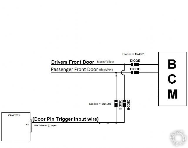
You will need 2 diodes ( 1N4001) to isolate the two door trigger connection to the Green (-) Door Trigger
Input wire ( bands towards the R/S ).
Think I would connect the Red +12V input wire from the relay pack to one of the trucks +12V constant
wire (Yellow ) and the ACC2 relay power and the other Red power wire ( w/15Amp fuse ) to the other +12V
constant wire ( GREEN/ Purple ) to split the load up.
The door lock wiring and connections are good if the truck came with Factory Keyless Entry.
One minor typo :
Pin 85 - Orange Ground when running (H2-1) Should be Ground When Armed
Pin 86 - Ignition (+) (Pink from main harness)
Pin 87a - ignition side of cut starter wire
Pin 30 - Vehicle side of cut starter wire
*Connect the remote start output (Purple) between the relay and the car!
------------- Soldering is fun!
Posted By: antman1
Date Posted: January 11, 2013 at 8:00 AM
Thank you.
I compared the wiring diagrams for 2004 and 2003 f150 models and they are mostly the same. I am thinking about not installing the starter kill relay in this one because it has the PATS system anyway.
As for the diodes I am not sure what you mean on the green door trigger. Are you talking about
8 Pin (H3) Harness:
7 - Green - blk/yel (L) or blk/pnk (R) - each door harness
not sure on that connection.
Also were would the 1100F connect to the alarm?
Posted By: kreg357
Date Posted: January 11, 2013 at 9:29 AM
1100F connections
Red +12V to ICBM 7071 Red @ 10 Pin Plug
Black Chassis Ground to ICBM 7071 Black @ 10 Pin Plug
Blue/White (-) 200mA Bypass Output to ICBM 7071 Blue/White (-) 200 mA Bypass Output @ 7 Pin Plug
Door Trigger :
------------- Soldering is fun!
Posted By: antman1
Date Posted: January 11, 2013 at 2:02 PM
Ok that diagram helps a lot. Thank you. So I will use 4 diodes total. I will have to separate the wires in the truck wire and place a diode in place on the drivers side wiring and passenger side wiring and also use diodes on the wires I have coming from Pin 7 Green.
I ordered some more supplies from ebay and I am waiting on the 1100F to come in then I will do my prep work and try to make it all pretty. I'll let you know if I have anymore questions. Thank you a lot for your help.
Posted By: antman1
Date Posted: January 11, 2013 at 2:49 PM
got another question. I know this requires a relay, how would I connect the relay?
6 Pin Secondary (H2) Harness:
Pin 87 - N/C
5 - BLACK/ White - Domelight Supervision Wire (+): BLACK/ Light Blue (Requires Relay)
Pin 85 - BLACK/ White (H2-5)
Pin 86 - ?
Pin 87a - ?
Pin 30 - ?
Pin 87 - ?
Sorry am drawing a blank on this.
Posted By: kreg357
Date Posted: January 12, 2013 at 3:19 PM
2003 F150 DOMELIGHT SUPERVISION BLACK/ LIGHT BLUE (+) IN PASSNEGER KICK PANEL
Extra 30/40 Amp SPDT relay to convert ICBM 7071 (-) output to (+) output for F150
Pin 85 - To ICBM 7071 BLACK/ White (H2-5) (-) 200mA Domelight Supervision Output
Pin 86 & Pin 87 +12V constant thru 5 Amp fuse
Pin 87a - Not Used
Pin 30 - F150 BLACK/ LIGHT BLUE (+) IN PASSNEGER KICK PANEL
-------------
Soldering is fun!
Posted By: antman1
Date Posted: January 12, 2013 at 4:40 PM
Thank you a lot. I think I have all the notes I need and I have cleaned them up a lot now and think I have it all set. Here is what I got if you wanna check it out: icbm7071-f150-install-notes.pdf
On the last relay for the 5amp fuse I am out of inline fuse holders. I am thinking I will solder direct to the 5amp fuse for pin 86 & 87.
I cant wait to get all my stuff I am waiting on to get this done.
Posted By: lucasoil4u
Date Posted: January 14, 2013 at 8:17 AM
Have fun with this unit. I installed 4 of these for one customer and within 3 weeks all 4 of these were junk. Ended up switching out all of them for artic start units. Hope these work well for you.
Posted By: antman1
Date Posted: January 14, 2013 at 11:00 AM
lucasoil4u wrote:
Have fun with this unit. I installed 4 of these for one customer and within 3 weeks all 4 of these were junk. Ended up switching out all of them for artic start units. Hope these work well for you.
This hasnt been the case for me. I installed one of these in my van back in March and it has been awesome. I have had no problems other than one of the key fobs quit working in August and I told the people I got it from on ebay and they said send it back to us and they sent me a new one. You can see my previous install page from here: https://www.the12volt.com/installbay/forum_posts.asp~TID~130600~KW~antman1~PN~1~TPN~1
Posted By: antman1
Date Posted: January 19, 2013 at 8:54 AM
I am noticing something I think I have wrong.
8 Pin (H3) Harness:
1 - GREEN/ Black Factory disarm - dk. GREEN/ purple - driver kick panel
2 - GREEN / WHITE Factory rearm - arms on lock w/door open
These 2 connections are for the factory alarm. I made sure the other day I don't have a factory alarm by rolling the window down and locking the doors with the factory keyfob then I waited a couple of minutes and reached in and unlocked and opened the door. no alarm when I did this. shouldn't those 2 connections be Not Connected?
Posted By: kreg357
Date Posted: January 19, 2013 at 9:12 AM
Correct. If the truck does not have the Factory Alarm, there would be no need to have the ICBM7071 try to arm / disarm it.
-------------
Soldering is fun!
Posted By: antman1
Date Posted: January 26, 2013 at 2:44 PM
I did my wire prepping yesterday and was gonna install it but it was raining. I wanted to confirm something though. Do I have the lock and unlock wiring right? Do I need a relay or is going to go direct like I have it?
10 Pin Primary (H1) Harness
3 - Violet - N/C
4 - Blue/Black - Power Door Unlock Negative Wire (-): Pink/Light Green
5 - BROWN / Black - Chassis Ground
6 - Violet/Black - N/C
7 - GREEN/ Black - Power Door Lock Negative Wire (-): Pink / YELLOW
8 - WHITE/ Black - Chassis Ground
Posted By: kreg357
Date Posted: January 26, 2013 at 3:14 PM
The ICBM7071 has built in relays. Your wiring is good if it's Type B (-) door locks ( F150 with Factory RKE ).
-------------
Soldering is fun!
Posted By: antman1
Date Posted: January 27, 2013 at 7:08 PM
kreg357 wrote:
The ICBM7071 has built in relays. Your wiring is good if it's Type B (-) door locks ( F150 with Factory RKE ).
Thank you kreg357, It was another cold rainy day so I will have to wait a bit longer. Wish I had a garage. I'll let you know how it goes.
Posted By: antman1
Date Posted: February 01, 2013 at 12:24 PM
Its a cold day but a good one so far, I am working on getting this installed but I have run into a snag or 2. I am very uncertain on the RX ECM, TX ECM and Ignition wires for the 1100F. Do you know exactly were this connector with the wires is located or what the colors and location are? Don't wanna screw the PATS system up. been reading horror stories on here while looking for it.
Other than that I just have these left:
domelight supervision wire,
Passenger door pin trigger wire,
Brake light positive wire,
door unlock wire (so far giving me a hard time to find)
door lock wire (so far giving me a hard time to find)
Tach wire under hood to Injector
Siren (Under hood)
Hood Pin Switch (Under hood)
Posted By: kreg357
Date Posted: February 01, 2013 at 3:34 PM
The Directed 1100F is pretty much the same install as the ADS TB FM2. Here is a link to it's install guide :
https://cdnprotected2.idatalink.com/corporate/Content/Manuals/TB-FM2/ADS-TB-FM2-EN_20130104.pdf?nvb=20130201205250&nva=20130201215250&hash=09bafb0d87bf9f3617b48
It gives the transponder connector diagram, connector location and wire colors you need.
Are the truck's wires matching up with the 2003 or 2004 F150? It is sometimes easier to get the lock wires
in the passenger kick panel. ------------- Soldering is fun!
Posted By: antman1
Date Posted: February 01, 2013 at 3:55 PM
kreg357 wrote:
The Directed 1100F is pretty much the same install as the ADS TB FM2. Here is a link to it's install guide :
https://cdnprotected2.idatalink.com/corporate/Content/Manuals/TB-FM2/ADS-TB-FM2-EN_20130104.pdf?nvb=20130201205250&nva=20130201215250&hash=09bafb0d87bf9f3617b48
It gives the transponder connector diagram, connector location and wire colors you need.
Are the truck's wires matching up with the 2003 or 2004 F150? It is sometimes easier to get the lock wires
in the passenger kick panel.
Thank you, I got everything except Domelight supervisor wire (wasnt sure how to check if I found the right wire in the passenger kick panel. had a black with light blue strip wire but I didnt get any voltage with the door open or close on it. Domelight Supervision isnt really needed though.
The PDF that you just referenced said I have a type 1-C connector located on the PATS harness. do you know about were to look for that harness? Also it said for that bypass module not to connect the Ignition wire to the connector at the PATS plug but to connect it to the vehicles ignition. Do I need to wire it there or the PATS Plug for the 1100F?
Posted By: antman1
Date Posted: February 01, 2013 at 3:57 PM
antman1 wrote:
kreg357 wrote:
The Directed 1100F is pretty much the same install as the ADS TB FM2. Here is a link to it's install guide :
https://cdnprotected2.idatalink.com/corporate/Content/Manuals/TB-FM2/ADS-TB-FM2-EN_20130104.pdf?nvb=20130201205250&nva=20130201215250&hash=09bafb0d87bf9f3617b48
It gives the transponder connector diagram, connector location and wire colors you need.
Are the truck's wires matching up with the 2003 or 2004 F150? It is sometimes easier to get the lock wires
in the passenger kick panel.
Thank you, I got everything except Domelight supervisor wire (wasnt sure how to check if I found the right wire in the passenger kick panel. had a black with light blue strip wire but I didnt get any voltage with the door open or close on it. Domelight Supervision isnt really needed though.
The PDF that you just referenced said I have a type 1-C connector located on the PATS harness. do you know about were to look for that harness? Also it said for that bypass module not to connect the Ignition wire to the connector at the PATS plug but to connect it to the vehicles ignition. Do I need to wire it there or the PATS Plug for the 1100F?
Forgot to metion they are matching 2003 f150 so far.
Posted By: kreg357
Date Posted: February 01, 2013 at 4:40 PM
I usually connect the 1100F Pink Ignition wire to the R/S's ( ICBM7071 in your case ) thick Ignition1 Output wire. It goes to the vehicles Ignition1 wire.
Here is a photo of an iDatalink bypass module ( similar to the 1100F ) mated to a R/S brain. You can see the ADS Pink Ignition wire going to the R/S's thick blue Ignition1 Output wire :
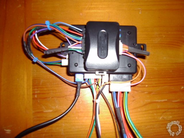
As for the transponder connector, it originates at the ignition switch. The connector you are looking for is located about 8" down the steering column from the ignition switch. ( As long as the transponder is the same as the 2003 model...)
Domelight Supervision isn't mandatory... ------------- Soldering is fun!
Posted By: antman1
Date Posted: February 01, 2013 at 6:01 PM
Thank you for the help. I have to say, I think the difficulty level of finding these wires was more than my Chrysler Town and Country. lol. I got most all of it completed and the alarm is working fine but I have to connect the Ignition wire and TX, RX wires tomorrow. I have been working at this for 10 hours and I am bushed. tomorrow I will have to make everything pretty and connect those wires. I tried the remote start with the key in the ignition and it turned on and turned off after 5 seconds. I think I have the wrong wire connected at the fuel injector. there is a red wire and a white wire. I connected it to the white wire and it may have a stripe on it too.
Were do you normally connect the Tach wire?
Posted By: kreg357
Date Posted: February 01, 2013 at 6:11 PM
Each F.I. should have two wires. Compare several F.I.'s. All should have one common colored wire. The other wire color is unique for each F.I. and that is the one you want to use. You can test / verify with a Digital Multi Meter. Set to 20 V AC, Red test lead on suspect wire, Black Test lead on chassis ground ( negative battery terminal ). With engine running, DMM should read between 1 and 6 volts at idle and increase with RPM's.
Follow the 1100F install guide. Start with a Factory Reset, then Step 1 ( Install Mode ) two-blinks and then Step 2A ( hopefully Type 1C ). ------------- Soldering is fun!
Posted By: antman1
Date Posted: February 02, 2013 at 2:09 PM
got it all installed and up in the dash. before I programmed the 1100F I tried to remote start and it never would fire up the engine only turned over. I programmed it and it fired up and ran for 5 to 6 seconds then off again. So I went back to looking for my tach wire. I tried my multimeter and it doesn't have 20 V AC setting. It had a 200 ACV and 500 ACV setting. I tried those and it said 30 and was staying the same even when revving the engine. I tried both wires on the coil pack and injector.
Posted By: antman1
Date Posted: February 02, 2013 at 3:07 PM
got it. the tach wire is now connected to GREEN / WHITE on the coil pack on the left side of the 4.6l engine. Alarm and remote start are working great. Thank you for all your help!
Some notes on this, lock and unlock wires I had to get from the passenger side up high in the dash. and also the passenger door trigger wire too. but I am glad it is done. :) Thank you again. Couldn't have done it right w/out your help.
Posted By: kreg357
Date Posted: February 02, 2013 at 3:37 PM
Good deal! Glad it's all set and working for you. Plenty of cold weather left. ------------- Soldering is fun!
|