Well that just sucks, I had a whole nice diagram made up and my damn computer froze just before I could save it. So I'm just going to put it in here.
5 Pin Heavy Gauge Harness:
Red - Red (+) 12v constant at ignition switch
Purple - Yellow (+) Starter wire at ignition switch
Orange - BLACK/ Orange (+) Accessory wire at ignition switch
Pink A - Dark Blue (+) Ignition wire at ignition switch
Pink B - N/C
*You will need to use a relay to power the 2nd accessory. Just a standard 30a/40a automotive relay connected as follows:
Pin 85 - Blue/White (-) bypass wire in H4 harness
Pin 86 - Orange Accessory wire from above
Pin 87 - 12v Constant Fused (can tie into fused Red 12v constant above)
Pin 30 - BLACK/ White (+) 2nd Accessory wire at ignition switch
7 Pin Secondary (H4) Harness:
1-3 - Factory wiring to R/S module
4 - Blue/White (See Above)
5 - Gray/Black - N/C
6 - BLACK/ White - Chassis Ground
7 - Violet/White - Gray or Gray/Red (AC) at ignition coil pack. Can also use the odd colored wire at any injector.
10 Pin Primary (H1) Harness
1 - Brown - To Siren (+) input
2 - White - GREEN / WHITE or GREEN/ Red (-) at headlight switch. Must set unit to (-) parking light output. Search for DEI Tech Doc 1080 if the van has automatic headlights.
3 - Violet - N/C
4 - Blue/Black - WHITE/ Green in left plug on bottom of BCM/Fusebox. Must connect a 665ohm resistor inline.
5 - BROWN / Black - Chassis Ground
6 - Violet/Black - N/C
7 - GREEN/ Black - Same as unlock wire. Must connect 4020ohm resistor inline.
8 - WHITE/ Black - Chassis Ground
9 - Red - 12v Constant fused (can tie into heavy gauge red wire from main harness)
10 - Black - Chassis Ground
6 Pin Secondary (H2) Harness:
1 - Orange - Starter kill relay input
*If you wish to enable the starter kill, you will need to cut the factory Yellow starter wire at the ignition switch and you will need another relay (same as above) connected as follows:
Pin 85 - Orange Ground when running (H2-1)
Pin 86 - Ignition (+) (Pink from main harness)
Pin 87a - ignition side of cut starter wire
Pin 30 - Vehicle side of cut starter wire
*Connect the remote start output (Purple) between the relay and the car!
Pin 87 - N/C
2 - Blue - N/C
3 - WHITE/ Black - N/C
4 - PURPLE / Black - N/C
5 - BLACK/ White - BROWN / white at dome light on/off switch
*This connection is not required, but if desired, it MAY require a relay
6 - RED / White - N/C
8 Pin (H3) Harness:
1 - GREEN/ Black - Factory alarm arm/disarm will require either 2 relays or a DEI 451m. The 451m is a better choice as it is more compact and will include a resistor pack. Connect the 451m as follows:
Violet/Black - Chassis ground
Blue/Black - Blue/Black unlock wire from unlock above(*Must connect between the unit and the resistor)
GREEN/ Black - GREEN/ Black lock wire from lock above (*Must connect between the unit and the resistor)
WHITE/ Black - N/C
BROWN / Black - N/C
Small Red - 12v Constant Fused
Small Blue - GREEN/ Black (H3-1)
Small Green - GREEN / WHITE (H3-2)
2 - GREEN / WHITE - See Above
3 - Red - I am not sure if this wire is needed along with the tach sensing or not. If so it will connect to the small wire coming off the alternator that reads 12v-14v only when the vehicle is running.
4 - Gray - Must add aftermarket hood pin.
5 - Brown - WHITE/ tan (+) at brake pedal switch
6 - Yellow - Pink wire from main harness
7 - Green - BROWN / Light Green at dome light on/off switch
8 - Purple - N/C
This is by no means an easy starter. Make sure to take your time and use a quality DMM to test EVERYTHING before making any connections. When making connections, strip, poke, solder, and tape the connection with a high quality 3m tape (super 33+ or better). If the tape is less than $2-$3 per roll then its no good!!!
Kenny
Owner / Technician
KKD Garage LLC
Albany, NY 12205


 Topic Closed)


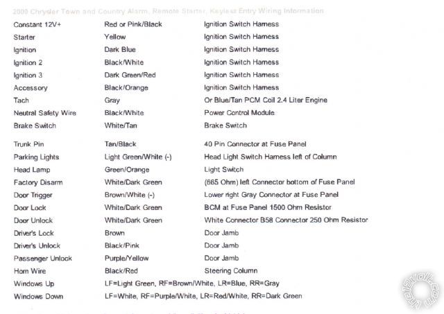 And this is the alarm I got yupbizauto 2 Way Car Security Alarm System LCD Remote Engine Start from ebay. I am including the wiring part of the book because I have not seen it posted anywhere else. I am not sure on what wire will go to what. I am a little confused by the directions on this install book and am in need of help.
Here is the wiring part of the book:
And this is the alarm I got yupbizauto 2 Way Car Security Alarm System LCD Remote Engine Start from ebay. I am including the wiring part of the book because I have not seen it posted anywhere else. I am not sure on what wire will go to what. I am a little confused by the directions on this install book and am in need of help.
Here is the wiring part of the book:


 If you can help please let me know, Thank you.


 Printable version


